Chapter 6 Setup Menu
118 Chapter 6 Setup Menu
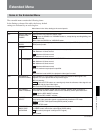
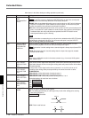
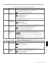
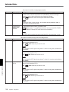
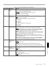
Extended Menu
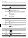
Item number Item name Settings
Menu items in the 700s, relating to video control
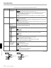
Item number Item name Settings
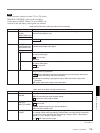
715 VIDEO GAIN
CONTROL
Adjust the video output level.
00H to 200H to 3FFH
Items 715 to 720 : Settings for controlling the video processing system according to the menu settings.
716 CHROMA GAIN
CONTROL
Adjust the chroma output level.
00H to 200H to 3FFH
717 CHROMA PHASE
CONTROL
Adjust the chroma phase.
00H to 80H to FFH
718
SETUP LEVEL
(DSR-2000A)/
BLACK LEVEL
(DSR-2000AP)
Adjust the setup level (DSR-2000A)/black level (DSR-2000AP).
00H to 200H to 3FFH
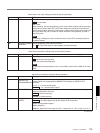
701
SELECTION OF
VIDEO/SYNC
DELAY
An E-E video signal is output delayed with respect to the video input signal by the time for
video circuit processing. With this item, select whether or not to delay the sync signal
attached to the output video signal by an amount corresponding to the video signal delay.
SYNC : Delay the sync signal by the corresponding amount before attaching it.
VIDEO: Attach a sync signal with the same timing as the input signal.
720
SYSTEM PHASE
SC
Adjust the subcarrier phase.
00H to 3FFH
705
EDGE
SUBCARRIER
REDUCER MODE
Select whether to enable the edge subcarrier reducer (ESR).
ON : Enable.
OFF : Do not enable.
When playing back a composite signal, set this to ON.
708 CHROMA PHASE
ROTATION MODE
Select the phase rotation mode for chroma phase control.
The effect of this setting applies to the output levels of all of the composite video, S
video, SDI and component video signals.
U/V : Select this setting when observing the unit's composite video output level using a
composite vectorscope.
PB/PR: Select this setting when observing the unit's component video output level using
a component vectorscope.
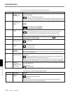
713 VIDEO SETUP
REFERENCE
(DSR-2000A only)
Select whether to remove the setup (7.5%) from the input analog video signals and
whether to add the setup (7.5%) to the output analog video signals.
714 VIDEO ADJUST
RANGE
Select the variable range of the VIDEO and CHROMA knobs when the PROCESS
CONTROL switch on the subsidiary control panel is set to PANEL.
–3~+3 : –3 dB to +3 dB
WIDE: – ∞ to +3 dB
Sub-item
INPUT LEVEL1
2
OUT PUT LEVEL
Whether to remove the setup from the input.
0.0% : Do not remove.
7.5%: Remove.
Whether to add the setup to the output.
0.0% : Do not add.
7.5%: Add.
710
INTERNAL VIDEO
SIGNAL
GENERATOR
Select the test signal to be output from the internal test signal generator.
CB100 (DSR-2000AP only): 100% color bar signal
CB75: 75% color bar signal
BB: Black burst signal
Default setting: CB100 (for DSR-2000AP)/CB75 (for DSR-2000A)
(Continued)


