


Chapter 1 Overview
Chapter 1 Overview 33
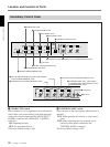
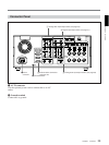
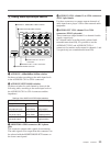
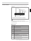
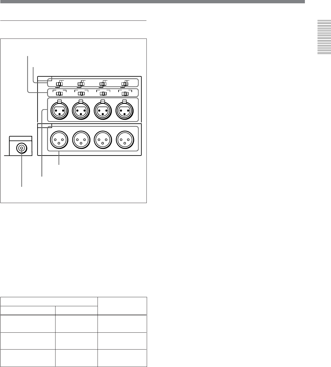
4 Analog audio input/output section
1 AUDIO IN −6dBm/0dBm/+4dBm switches
Set these switches according to the audio input levels
to the AUDIO IN CH-1 to CH-4 connectors.
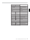
2 AUDIO IN LEVEL/600Ω switches
Set these switches for each channel as shown in the
following table, according to the audio input levels to
the AUDIO IN CH-1 to CH-4 connectors and the
impedance.
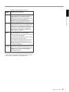
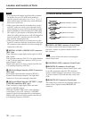
Settings of the AUDIO IN LEVEL/600Ω switches
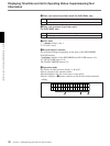
3 MONITOR AUDIO connector (RCA phono
jack)
This connector outputs audio signals for monitoring.
The audio signals to be output from this connector can
be selected with the MONITOR SELECT buttons on
the lower control panel.
Audio input
Switch setting
Level Impedance
−60dBs
(microphone input)
High impedance
(about 20kΩ)
LOW-OFF
(left position)
+4dBs/0dBs/−6dBs
(line audio input)
High impedance
(about 20kΩ)
HIGH-OFF
(middle position)
+4dBm/0dBm/−6dBm
(line audio input)
600Ω HIGH-ON
(right position)
MONITOR AUDIO
AUDIO IN
LEVEL
AUDIO OUT
CH-1
CH-2 CH-3
CH-4
CH-1
0dBm
HIGHLOW
OFF
-6dBm +4dBm
CH-2 CH-3
CH-4
0dBm
-6dBm +4dBm
0dBm
-6dBm +4dBm
0dBm
-6dBm +4dBm
ON
-600
Ω
LEVEL
HIGHLOW
OFF
ON
-600
Ω
LEVEL
HIGHLOW
OFF
ON
-600
Ω
LEVEL
HIGHLOW
OFF
ON
-600
Ω
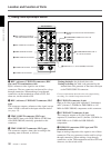
1 AUDIO IN −6dBm/0dBm/+4dBm switches
2 AUDIO IN LEVEL/600Ω switches
3 MONITOR AUDIO connector
4 AUDIO IN CH-1 to CH-4 connectors
5 AUDIO OUT CH-1 to CH-4
connectors
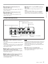
4 AUDIO IN CH-1 (channel 1) to CH-4 connectors
(XLR 3-pin, female)
Use these connectors to connect separate channels of
audio input from a player VCR or other external audio
equipment.
5 AUDIO OUT CH-1 (channel 1) to CH-4
connectors (XLR 3-pin, male)
These connectors output channel-1 to channel-4 audio
signals, respectively.
In 2-channel audio recording mode (selected with
extended menu item 818), it is possible to use the
AUDIO OUT CH-3 and AUDIO OUT CH-4
connectors for monitor audio output for channels 1 and
2, respectively (use extended menu item 820).