Chapter 1 Overview
26 Chapter 1 Overview
Location and Function of Parts
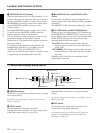
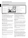
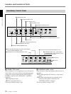
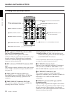
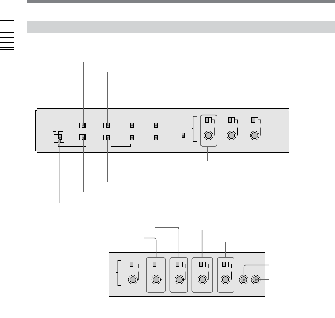
Subsidiary Control Panel
OFF ON
CHARACTER
EXT INT
CONTROL PANEL
TC GENERATOR
NDF DF
ON OFF
REC INHIBIT
VITC
OFF ON
ON OFF
KEY INHIBIT
PROCESS
CONTROL
VIDEO
TC SELECT
MENU
PRESET
MANUAL
VITC TC
REC FREE
EXT INT
REMOTE LOCAL
RUN RUN
REGEN PRESET
CHROMA
PRESET
MANUAL
SET UP
PRESET
MANUAL
VIDEO
PRESET
MANUAL
CHROMA
PRESET
MANUAL
SET UP
PRESET
MANUAL
Y/C DELAY
PRESET
MANUAL
CHROMA PHASE
(HUE)
PRESET
MANUAL
SYNC
SYSTEM PHASE
SC
1 CHARACTER switch
2 CONTROL PANEL switch
3 REC INHIBIT switch
4 KEY INHIBIT switch
5 PROCESS CONTROL switch
6 INT/EXT−PRESET/REGEN switch
7 FREE RUN/REC RUN switch
8 DF/NDF switch (DSR-2000A only)
9 VITC switch
!º TC SELECT switch !¡ VIDEO knob and PRESET/MANUAL switch
!£ CHROMA knob and PRESET/MANUAL switch
!™ SET UP (DSR-2000A)/BLACK LEVEL (DSR-2000AP)
knob and PRESET/MANUAL switch
!¢ Y/C DELAY knob and PRESET/MANUAL switch
!∞ CHROMA PHASE (HUE) (DSR-2000A)/
CHROMA PHASE (DSR-2000AP) knob and
PRESET/MANUAL switch
!§ SYNC knob
!¶ SC knob
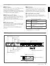
1 CHARACTER switch
Select whether or not to superimpose text information
such as time code, menu settings, and alarm messages
on the video signal output from the SDI OUTPUT 3
(SUPER) connector and VIDEO OUT 3 (SUPER)
connector.
ON: Superimposed text
OFF: No superimposed text
The factory default setting is ON.
2 CONTROL PANEL switch
Select the state of the control panel when this unit is
operated.
INT: When operating this unit by its own control
panel.
EXT: When operating this unit remotely by an
optional control panel connected to the
CONTROL PANEL connector.
The factory default setting is INT.


