13
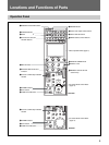
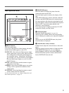
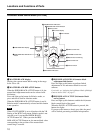
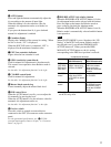
8 SENS (sensitivity) control knob
Used for manual iris adjustment in Absolute mode.
This control is not operative when Relative mode is
selected.
See the table “Iris adjustment functions”on page 11.
9 COARSE control knob
Used for manual iris adjustment.
See the table “Iris adjustment functions” on page 11.
0 IRIS control
When the AUTO button is not lit, you can adjust the
iris manually by turning the control.
When the AUTO button is lit, the reference value for
automatic iris adjustment can be set with this control.
See the table “Iris adjustment functions” on page 11.
qa Iris gauge
Turn the gauge to set the line to the most frequently
used iris position, and it can be used as the reference
for manual iris adjustment.
qs AUTO button
Press and light the button to automatically adjust the
iris according to the amount of input light.
When this button is lit, the reference value for
automatic iris adjustment can be set with the iris
control.
If you press the button when lit, it goes dark and
manual iris adjustment is enabled.
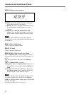
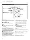
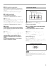
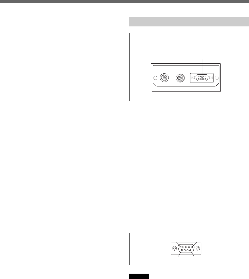
Connector Panel
1 MONITOR connector (BNC type)
Connect to a video monitor.
2 CCU/CAMERA (camera control unit/camera)
connector (10-pin)
Connect to the REMOTE connector of a camera
control unit or a camera.
3 EXT I/O (external input/output) connector
(9-pin)
This connector permits you to control an external
device using the PREVIEW button (
page 6) or the
preview switch (
page 11).
Operational specifications
While the PREVIEW button or the preview switch
(RCP-D50 only) is held pressed, pin 1 and pin 2 of the
EXT I/O connector are short-circuited.
Pin assignment of the EXT I/O connector
Caution
When installing this panel, provide a gap of 7 cm (3
inches) or more behind the connector panel to prevent
damage to cables.
3EXT I/O connector
1MONITOR connector
2CCU/CAMERA connector
MONITOR
CCU/
CAMERA
EXT I/O
1
6
5
9


