


Installing the Equipment
Instruction Manual: evolution 5000 E57xx DSNG and DENG Voyager Encoder Page 2-13
ST.TM.E10076.3
Do not move or install equipment whilst it is still attached to the mains
supply. Ensure ESD precautions are observed whilst interconnecting
equipment.
NOTE…
See Chapter 3 for information relating to Options and Upgrades.
2.6.3 Power Supply
Section 2.4, AC Mains Operating Voltage and Earthing provides details of
power supply connection, Protective earthing and safety. Read all the
instructions carefully and take note of all warnings and cautions. Also, see
Section 2.5, DC Operating Voltage and Earthing.
2.6.4 Technical Earth
Connect the Encoder's Technical earth to a suitable point.
2.6.5 Video Inputs
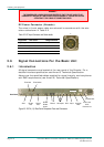
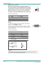
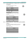
SDI IN
A 75 W BNC connector provides a serial digital video
input to the unit. See Chapter 4, Operating the
Equipment Locally, Video Input Option for the types of
video and selection method. This input is terminated in
75 W.
The serial input supports error detection and handling (EDH) as defined by
the specification SMPTE RP 165-1994, ‘Error Detection Checkwords and
Status Flags for Use in Bit Serial Digital Interfaces for Television’.
For more information about EDH refer to Annex K, EDH Capability for
E57xx Encoders.
Table 2.3: SDI Connector
Pin Signal
Centre Video Input
Screen Ground
Impedance 75 W
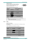
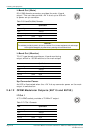
H SYNC
Studio Black and Burst should be fed to the 75 W BNC
connector (H SYNC). This will then genlock the
Encoder to the Studio system. This method may be
required with some audio formats, or for locking
Encoders to an evolution 5000 Multiplexer. For details
on the genlocking system see Annex G, Audio Modes.