


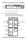
Installing the Equipment
Instruction Manual: evolution 5000 E57xx DSNG and DENG Voyager Encoder Page 2-15
ST.TM.E10076.3
Table 2.6: Audio In Connector
Pin Signal Pin Signal
Analogue Digital Analogue Digital
1 Left Channel A (+) AES/EBU (A) (+) 9 Left Channel A (-) AES/EBU (A) (-)
2 Not connected 10 Right Channel A (+)
3 Right Channel A (-) 11 Not connected
4 Left Channel B (+) AES/EBU (B) (+) 12 Left Channel B (-) AES/EBU (B) (-)
5 Not connected 13 Right Channel B (+)
6 Right Channel B (-) 14 Not connected
7 AES/EBU
Reference (Signal)
15 AES/EBU
Reference (Ground)
8 Not connected
NOTES…
1. In analogue mode termination is either 20 kW or 600 W.
2. In AES/EBU mode termination is 110 W.
3. When the Encoder is powered down the digital channel is selected with 110 W termination.
4. The digital audio input does not support SPDIF.
5. In order to comply with EMC regulations, use the audio break-out cable supplied with the unit.
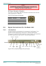
2.6.7 ASI OUT 1, 2 and 3 Outputs
Connect the Multiplexer or Modulator ASI cable to the
appropriate ASI OUT connector, using good quality
75 W coaxial cable (for example, BBC PSF 1/3).
A 75 W BNC connector provides the output from the Encoder.
Table 2.7: ASI OUT 1, 2 and 3 Connectors
Pin Signal
Centre Signal
Screen Ground
2.6.8 Control Interfaces
Connection
Operation of the Encoder from a TANDBERG Television control system is
via the Ethernet network running the Simple Network Management
Protocol (SNMP) protocol. Connect the ETHERNET connector to the
controller (for example, MEM). Local control is implemented through the
front panel keypad and display. See Chapter 4, Operating the Equipment
Locally for details of how to access the front panel menus.