


14
Introduction
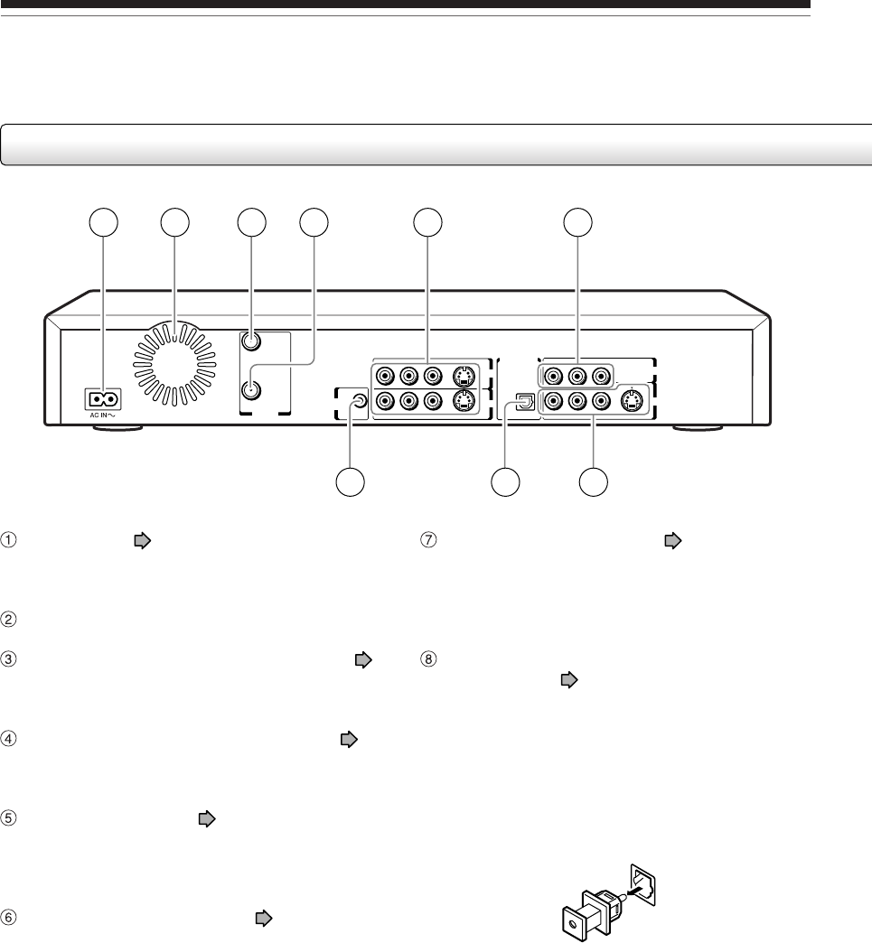
Index to parts and controls (Continued)
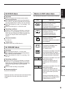
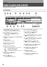
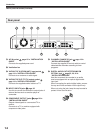
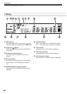
Rear panel
P
B
P
B
VHF/UHF
VIDEOLR VIDEORL
R L VIDEO
S-VIDEO S-VIDEO
S-VIDEO
P
B
Y
P
R
COMPONENT OUTPUT
OUTPUT
INPUT3
INPUT1
RF OUT
(TO TV)
RF IN
(FROM ANT.)
IR
DIGITAL AUDIO OUTPUT
BITSTREAM/PCM
OPTICAL
CHANNEL
CHANGE
1 4 52 3 6
97 8
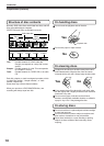
CHANNEL CHANGE IR jack page 19 in
“INSTALLATION GUIDE”
Connect the supplied IR control cable to control
cable/satellite channels according to timer
programs.
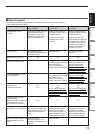
DIGITAL AUDIO OUT BITSTREAM/PCM
OPTICAL jack
page 22, 23, 24 in
“INSTALLATION GUIDE”
Use this to connect the recorder to an audio
receiver equipped with an optical digital audio
input jack.
When connecting the optical digital cable, remove
the cap and fit the connector into the jack firmly.
When not using the jack, keep the cap inserted to
protect it from dust intrusion.
AC IN socket page 15 in “INSTALLATION
GUIDE”
Connects the supplied power cord.
Ventilation fan
VHF/UHF RF IN (FROM ANT.) input socket
page 14 in “INSTALLATION GUIDE”
Connects to an antenna or cable signal.
VHF/UHF RF OUT (TO TV) output socket
page 14 in “INSTALLATION GUIDE”
Connects the supplied coaxial cable to a TV.
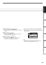
INPUT1/INPUT3 jacks
page 36
Use this to connect the recorder to output jacks of
external devices such as another player or
camcorder.
COMPONENT OUTPUT jacks
page 20 in
“INSTALLATION GUIDE”
Outputs video signals to a connected TV or
monitor.
Connects to a TV or monitor equipped with
component video jacks.