


47
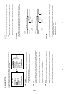
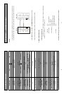
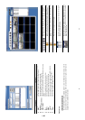
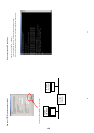
RJ-45 PIN configuration for Ethernet
PIN NO. PIN Assignment
1. TX +
2. TX -
3. RX +
4. Not Connected
5. Not Connected
6. RX -
7.
Not Connected
8.
Not Connected
Physical specification for Ethernet
Wire Type Cat. 5
Connector Type
RJ-45
Max. Cable Length 30 M
Hub Wiring Configuration Straight Through
PC Wiring Configuration Cross Over
NOTE: For more details on network connections, please refer to APPENDIX 5
1.2 Install the Network Viewer to your PC
Install the Network Viewer from the included CD.
1. Exit all applications currently running on the chosen PC.
2. Insert the included CD in the CD-ROM drive; the program will execute installation automatically and then
follow the on-screen instructions to proceed with the rest of the installation procedures when it appears.
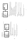
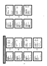
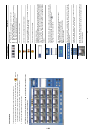
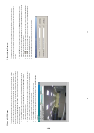
3. After installation is complete, click on the START menu from your computer, point to Programs/ Picture
Viewer to open up the program selection page as shown below. Click the Network Viewer icon to start
the Network Viewer program.
Install the Network Viewer from the ZIP file.
1. Save the ZIP file to your PC and extract the file to a designated directory.
2. Open the extracted folder. The folder contains 5 files.
3. Click on the
to execute installation and then follow the on-screen instructions to proceed with the
rest of the installation procedure when it appears.
4. After installation is complete, click on the START menu from your computer, and point to Programs/
Picture Viewer to open up the program selection page as shown below. Click the Network Viewer icon
to start the Network Viewer program.
1 2 3 4 5 6 7 8
RJ-45 socket
48
NOTE: Please make sure the TCP/IP communication software has been properly set and configured
in your computer. To check your TCP/IP settings, refer to APPENDIX 5
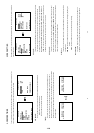
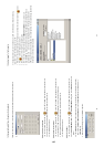
1.3 View DVR Video From A Remote PC
Follow the instructions below to use the Network Viewer to browse a DVR video from a remote location.
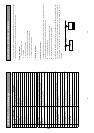
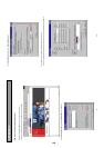
Upon entering the Network Viewer; the connection box will appear as follows.
1. Choose a channel number from the Channel drop-down list.
2. Assign a name for the chosen DVR.
3. Type in the password and IP of the device and click the Add button to add the device to the
connection list.
4. Click the Connect button to establish the connection between the devices and the computer. To begin
viewing images, click OK.
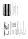
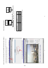
NOTE: Upon connection, the connection status box indicates the name and IP address of the
selected device. If unable to connect, a “Fail” message appears on the screen right after
the device IP address; otherwise an “OK” appears. To add more connections or units of the
DVR, please repeat the above instructions.
NOTE: Please refer to APPENDIX 5 for details about proxy settings and network connections
checking.
1-24