


9
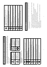
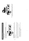
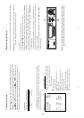
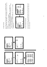
2.2 Rear View
MUX MAIN MONITOR IN Connector:
This BNC connector is used to connect the live video output from a multiplexer to the unit.
VIDEO IN Connector:
This BNC connector is used to connect the video output from a camera or a multiplexer to the unit.
S-VIDEO IN Connector:
This connector is used to connect the S-video output from a camera or a multiplexer to the unit.
Terminal Block:
There are 9 exposure contacts on this terminal block including SW. Out, GND, ALM. OUT, FULL,
REC, ALM RST, GND, and ALM. IN for connecting with external devices. Please refer to the next
section for details.
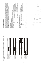
Power Switch:
To power the unit on or off.
Plug Outlet:
For connecting with an external power supply.
RS-232 Port:
RS-232 communication port for connecting with an external control device. Please refer to
APPENDIX 1 for more details.
S-VIDEO OUT Connector:
This provides a S-video signal to a multiplexer.
VIDEO OUT Connector:
This provides a composite video signal to a multiplexer.
MONITOR Connector:
This provides a composite video or a multiplexer’s live signal if connected to a display device.
10 BASE-T Connector:
This is a standard RJ-45 connector for 10 Mbps Ethernet networks.
NOTE: The DVR only processes the S-VIDEO IN signal when receiving video signals
simultaneously from both “S-VIDEO IN
” and “VIDEO IN ” connectors.
10
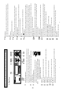
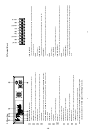
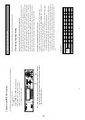
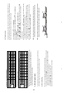
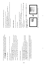
2.3 Terminal Block
123456789
ALM.IN
GND
ALM.RST
REC
GND
FULL
ALM.OUT
GND
SW.OUT
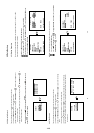
1. ALM IN: (INPUT)
This is an alarm input, which can be programmed in the menu system to Normally Open or Normally
Closed. (Active low, 5V)
2. GND:
Ground Contact.
3. ALM RST: (INPUT)
This terminal connects to an alarm-clear device for clearing the alarm. (Active low, 5V)
4. REC: (INPUT)
This terminal connects an external switch to turn the recording function of the DVR on/off. (Active low,
5V)
5. GND:
Ground Contact.
6. FULL: (OUTPUT)
This terminal sends out the full-disk signal. (Active low, 5V)
7. ALM OUT: (OUTPUT)
This is an alarm output relay. Connect this to an external device like buzzers or lights. (Active low, 5V)
8. GND:
Ground Contact.
9. SW OUT: (OUTPUT)
This terminal, sending out the timing signal (falling/negative) to a multiplexer. Connect this terminal to a
multiplexer’s trigger terminal so that the multiplexer can switch to use the same recording speed as the
DVR.
1-5