


4-6
Using the HP/Agilent 83210A Service Kit
Making Measurements
Making Measurements
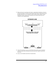
Audio / Digital Assemblies
The extender boards for the audio and digital assemblies allow the boards to be extended
above the instrument. This provides better access to signals going to and from these
assemblies. Refer to the “Block Diagrams” (chapter 13) or “Module I/O Specs”
(chapter 12) for pin numbers and typical I/O characteristics for each assembly. Use the
extender board shown.
RF ASSEMBLIES
The extender boards for the RF assemblies extend the modules above the instrument. This
allows better access to control signals and allows the RF input and output signal paths to
be opened for making measurements. The following procedure outlines the steps
necessary to make measurements on the RF modules with the RF extender board.
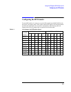
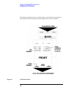
1. Configure the RF extender card with the proper coax jumpers. Refer to table 4-2 and
figure 4-1.
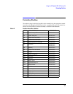
2. Decide the signal path that needs to be measured. Find the correct plug number and pin
number on the “Block Diagrams” (chapter 13) or “Module I/O Specs” (chapter 12).