


5-6
Troubleshooting the Controller/Display
Keyboard
Keyboard
The A1 Keyboard assembly contains both the keys and the knob. The keyboard is
configured in a matrix with the rows being scanned with pulses from the A7 Controller
and the columns being read by the controller. The column lines are pulled up through
resistors and are pulled low when a key is pressed. The A7 Controller determines which
key is being pressed by reading which column line is pulled low and which row the
column line is being pulled low through. Since the row outputs are tri-state, the low-going
pulses are not seen on the output until a key is pressed and the current path is completed.
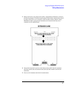
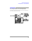
The keyboard can be checked with an oscilloscope by disconnecting the ribbon cable from
the keyboard and checking for the pull-up voltages on the column pins. Then with the
keyboard connected, check that the lines are being pulled low at the A7 Controller
connector J4. The pin numbers on A7-J4 are the same as those on A1-J1. The ribbon cable
connector has a mark to indicate to pin 1. Pin 2 is directly opposite pin 1.
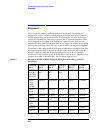
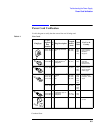
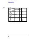
Table 5-1 HP/Agilent 8922E/F/G/H/M/S Keyboard (HP/Agilent 8922 A/B keys shown in
parenthesis)
Column 0
Pin 9
Column 1
Pin 10
Column 2
Pin 11
Column 3
Pin 12
Column 4
Pin 13
Column 5
Pin 14
CELL
CONFIG
(RF GEN/
RF ANL)
ORGCALL
(K1)
RCVCALL
(K2)
ENDCALL
(K3)
L1(K4) L2(K5)
CELL
CNTL
(HOP
CNTRL)
INCR÷10 down arrow not used SHIFT CANCEL
MEAS
SYNC
INCRSET PRESET not used not used not used
PREV INCR×10 up arrow not used not used leftarrow
TESTS 7 4 1 0 ON/OFF
MEAS
ARM
8 5 2 . ppm W
RECALL 9 6 3 +/- % dBµV
LOCAL ENTER GHZ dBm MHz V kHzmV Hz µV