


8-4
Assembly and Disassembly Procedures
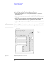
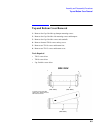
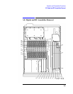
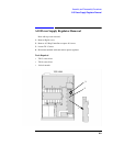
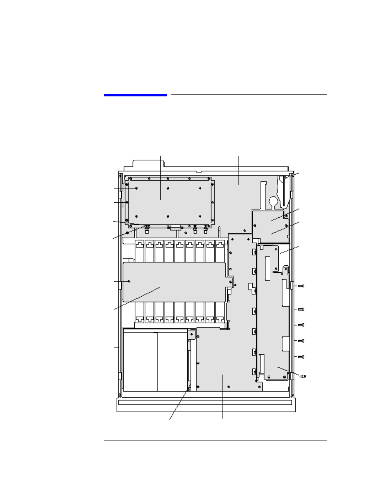
Inside Protective Covers
Inside Protective Covers
All covers can be removed with a TX-15 screw driver. Screws shown circled only require
loosening.
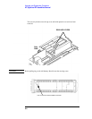
12 CRT Bracket
426
3
424
416-
421,
427-
456
502-
504
Nut
499-
501
Washer
506-
521
493-
498
114 Regular
Mounting
Bracket and
115-118
Screws
(Not Shown)
458
(Opt. 001)
244
240 GPIB
Mounting
Bracket and
241-242
Screws
252
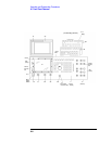
492 Top Cover (B, E and G)
505 Bottom Plate (B,E and G)