


5-3
Troubleshooting the Controller/Display
Parallel Bus
Parallel Bus
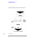
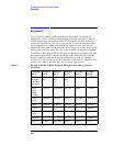
The parallel bus is at the center of the control section. The parallel bus is defined as direct
connections to the A7 Controller. These connections include the data bus, address bus and
dedicated parallel control lines.
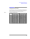
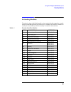
The assemblies on the parallel bus are:
• A1 Keyboard
• A6 Signalling Source/Analyzer
• A7 Controller
• A8 Memory
• A9 Global Test/Demod
• A19 Measurement Board
• A20 CRT Driver
• A21 GPIB Interface
• A32 GSM Controller
• A33 Hop Controller
Most problems with the parallel bus are accounted for in the power-up self-tests. The self-
tests check the A7 Controller first, then the A8 Memory. If these two tests pass, the
instrument will beep once after approximately 10 seconds. If these tests do not pass, the
problem is probably on one of the two boards or something is pulling down the parallel
bus.
The assemblies that are not directly checked by the power-on self-tests are the A1
Keyboard and the A21 GPIB Interface.