


Section
3
Listener lnput Format
3.1
Listener lnput Program Message Format
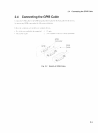
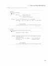
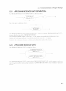
The following section shows program messages when, for example,
4
UI
is selected for the reception jitter and the
reception signal is set to
9953M.
<TERMINATED PROGRAM MESSAGE,
*ddreSS
3
L~stener address spec~ficat~on
<PROGRAM MESSAGE, <PROGRAM MESSAGE TERMINATOR>
A
vA,
:
SENS
:
TEL
:
RANG
U14
S
P
T
I
/
'\
<COMMAND PROGRAM HEADER>
\
'
~whlte space,
:
SENS :TEL: RANG
\
'\
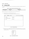
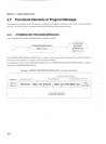
Listener
(device)
<PROGRAM MESSAGE UNIT> <PROGRAM MESSAGE LiNlT SEPARATOR, <PROGRAM MESSAGE UNIT>
SP
<NL>
;
SP
:
SENS
:
TEL
:
BRAT
~9953-
,r
i
,
;
<wh~te space>
<COMMAND PROGRAM HEADER,
:
SENS
:
TEL
:
BRAT
\
,/
'\
/
WRITE
@03
:
":
SENS
:
TEL
:
RANG U14
;
:
SENS
:
TEL
:
BRAT
M9953"
eNL>
I
.r
----
7
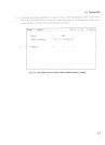
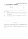
<PROGRAM HEADER SEPARATOR, <PROGRAM DATA,
SP
<program mnlrnonlc>
SENS TEL RANG
t
i
7
Talker
(controller)
I
I
'\\
<PROGRAM HEADER .;PROGRAM DATA,
SEPARATOR,
<wh~te space> 'boolean program data>
U14
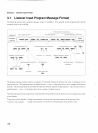
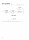
The program message format comprises a sequence of functional elements divided into the units of minimum level to
express functions. The uppercase letters in angled brackets
(
<
and
>
)
in the figure above show examples of functional
elements. The functional elements are further divided into elements called the coding elements. The lowercase letters in
angled brackets
(
<
and
>
)
in the figure above show examples of coding elements.
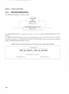
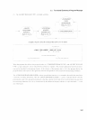
The following pages provide explanations of the program message format using the functional syntax diagram and coding
syntax diagram.
Functional syntax diagram: Graphic representation of selection of functional elements along specific routes
-
Coding syntax
diagram:
Graphic representation of selection of coding elements along specific routes