


10
CFA3000 ISE Analyzer
Instruction Manual
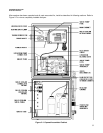
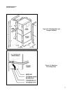
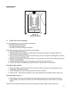
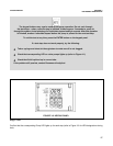
Electrical connections are made to and from the cabinet at the input/output panel, located on the left side of the
analyzer. See Figure 25.
• Terminals are provided for ground, power supply, high/low alarms, output signals, calibration and status
relays
• Output signals a voltage output of 05 Vdc and a floating, ungrounded current output of 420 mA are
available for remote readout or control of a process.
• Also available are contact closures for the following:
High alarm Calibration
Low Alarm Leak Alarm
To make electrical connections, proceed as follows:
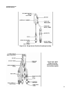
1. Remove solid caps from the holes above the input/output panel by puncturing with an awl and prying
them out. (Note: remove caps only from those holes that will be used.)
2. Replace with permanent connectors.
3. Connect alarms and external computer interfaces (if any).
4. Feed 3wire power cable into analyzer through hole above the input/output panel.
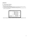
5. Connect wires to appropriate contacts on Terminal Strip TB3.(See next page)
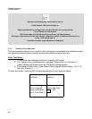
2.6 Prepare Electrical Connections
Use cable glands to hold cables securely in holes above input/output panel.
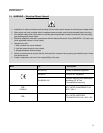
WARNING:
Connect output signals, if any before connecting the power supply.
CAUTION:
For proper operation and for safety, electrical connections to this equipment must be
made in accordance with local or national electrical code as applicable.
This equipment must be grounded. A qualified electrician should wire this equipment to an
electrical circuit.