


iii
TABLE OF CONTENTS (CON’T)
CFA3000 ISE Analyzer TABLE OF CONTENTS
Instruction Manual
LIST OF FIGURES
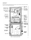
Figure 21 Opened Assembled Cabinet ....................................................................................5
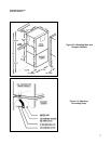
Figure 22 Mounting Main and Reagent Cabinets ....................................................................7
Figure 23 Attaching Grounding Strap.......................................................................................7
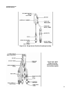
Figure 24a Singlestream Overflow Sampling Assembly...........................................................9
Figure 24b Multistream Overflow Sampling Assembly.............................................................9
Figure 25 Input/Output Panel..................................................................................................11
Figure 26 Valve Pump Assembly............................................................................................12
Figure 27 Pump Connectors ..................................................................................................12
Figure 28 Sample Bottle Placement in Cabinet (for all methods; colors refer to
reagent straw colors)..............................................................................................13
Figure 31 Simple Block Diagram............................................................................................14
Figure 32 Numbered Positions on a SingleStream Keypad.................................................17
Figure 33 Valve Pump LED Designations..............................................................................19
Figure 34 Logic Flow for Singlestream Parameter Definition...............................................20
Figure 35 Logic Flow for Multistream Parameter Definition .................................................21
Figure 61 Remove Valve Pump Assembly.............................................................................31
Figure 62 Card Cage ..............................................................................................................32
Figure 63 ISE Reaction Cell Assembly, Electrodes ...............................................................33
Figure 71 Analyzer Front View ...............................................................................................35
Figure 72 Card Cage and Boards ..........................................................................................38
Figure 73 Analog Board DIP Switches (with #3 set in OFF position for multi..........................
stream analyzer)....................................................................................................39
Figure 74 Electrical Wiring and Components in Rear Cabinet..............................................40
Figure 75 Valve Pump Assembly............................................................................................41
Figure 76 Interface Ports ........................................................................................................42
Figure 77 "D" Connector for Relay Output.............................................................................42
Figure 78 SingleStream Overflow Sampling Assembly........................................................43
Figure 79 Multistream Overflow Sampling Assembly (threestream option)........................44
Figure 81 Input/Output Panel .................................................................................................45
Figure 82 Typical Trace Recording with Calibration of Single Stream System.....................46
Figure 83 Typical Stream Trace Recording with Calibration of Multistream
System....................................................................................................................47
Figure 84 Numbered Positions on a SingleStream Keypad................................................49
Figure D1 Calibration Bypass Wiring......................................................................................56
Figure E1 Keypad Panel for Single Stream Option................................................................57
Figure E2 Number Positions on a SingleStream Keypad....................................................57
Figure E3 Keypad Panel for Multistream Option...................................................................60