


42
CFA3000 MANUAL SECTION 7
INSTRUMENT DESCRIPTION
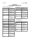
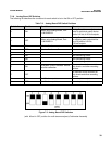
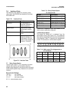
Port Function
RS232C For connection of
computer interface or
other accessories
Relay Output Optional relay contact
(multistream analyzer
only)
Printer For connection of printer
cable
Recorder For connection of
external recorder; for
multioutput, 420 mA
and 05 Vdc outputs for
streams 2 through 6.
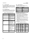
Pin No. Description
1 NO 9 C Stream #1 Alarm or ID
2 NO 10 C Stream #2 Alarm or ID
3 NO 11 C Stream #3 Alarm or ID
4 NO 12 C Stream #4 Alarm or (#1*) ID
5 NO 13 C Stream #5 Alarm or (#2*) ID
6 NO 14 C Stream #6 Alarm or (#3*) ID
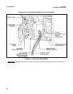
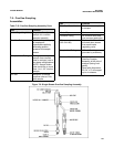
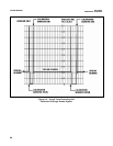
7.6 Interface Ports
The interface ports (labeled for recorder, printer,
relay output, and RS232) are located on the lower,
left outside wall.
Table 712: Interface Ports
If there are 3 streams or less, both stream ID and
alarms may be optionally configured.
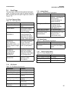
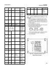
7.8 MultiOutput Board
The output for Stream #1 is obtained from the
Input/Output Panel (see Figure 25). The additional
five outputs are obtained from the lower lefthand side
of the analyzer. Table 714 gives the pin assignments
on the “D” connector for a multistream system:
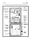
Figure 76. Interface Ports
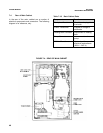
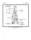
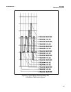
7.7 Relay Output Option
This port (see Figure 77) is a collection of contact
closures that can be used to identify either the
stream being displayed or the alarm that is activated
(multistream systems only). these are not “powered”
contacts.
Relay Contact Ratings:
100 Vdc max voltage
10 Vdc max DC current
1.0 A max carry current
0.5 A max switched current
Table 713: Relay Output Option
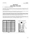
Pin Assignments
\ 1 2 3 4 5 6 7 8 9 10 11 12 13 14 /
\
15 16 17 18 19 20 21 22 23 24 25 /
Figure 77. "D" Connector for Relay Output
Table 714: Multioutput Pin Assignments on
“D” Connector
2 15 2 14 1
3 17 4 16 3
4 19 6 18 5
5 21 8 20 7
6 23 10 22 9