


55
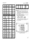
The block diagram in Figure C1 graphically shows
the distribution of power and signals throughout the
analyzer. The raised numbers (e.g., (6) ) in the
description below relate to the circled numbers on the
diagram. For clarity, minor components such as fuses
are not shown.
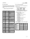
1. For 110 Vac 50/60 Hz option, line power enters
the analyzer at the Power Entry barrier strip TB3 (1),
with the following connections (refer to Figure 25
and Figure C1):
• Line (hot) connection is TB31
• Neutral is TB32
• Safety (chassis) ground connection is TB34
For 220 Vac 50/60 Hz option, the following con
nections are used:
• L1 connection is TB37
• L2 connection is TB38
• Safety (chassis) ground connection is TB34
2. For 110 VAC 50/60 Hz option, line power flows
through the Power Switch and other minor compo
nents to barrier strip TB1. TB1 serves as the line
power distribution point.
For 220 VAC 50/60 Hz option, line power flows
through the Power Switch and other minor compo
nents to the primary of the stepdown Transformer (2).
The Stepdown transformer converts the input 220
VAC to 110 VAC for compatibility with the standard
CFA3000 electronics. From the Stepdown
Transformer secondary power flows to barrier strip
TB1.
3. From TB1, for both options, line power flows to
the Colorimeter Lamp Power Supply, (4) , the Power
Transformer (3) , the Pump Power Supply (5) and the
Power Supply Board (8e) located in the Card Cage (8).
4. The Colorimeter Lamp Power Supply produces
highly regulated DC current which energizes the
Colorimeter Lamp (4a).
5. The Power Transformer converts standard line
voltage to lowvoltage AC for use by the CFA3000
electronics. The Power Transformer secondaries feed
the Power Supply Board, which converts the lowvolt
age AC to regulated DC current, and to the heater
element in the Heating Bath (7) . Relay contacts on
the Power Supply Board are externally available at
the I/O Panel (10) for activation of alarm and status
indicators.
Multistream Analyzer Option
In units equipped with the Multistream option, a
Valve Board (8c) will be installed. This board contains
relay contacts that are externally available at the
Interface Ports (11) as well as LED drivers to activate
the sample stream indicators located on the Keypad
Panel (9) . The Valve Board also provides interfaces
for a printer and serial data communications, exter
nally available at the Interface Ports.
If the monitor includes a multioutput analog board,
analog recorder drivers for each stream are installed
on the Analog Board (8d) . These outputs are exter
nally available at the Interface Ports.
APPENDIX C POWER INTERCONNECT DESCRIPTION
CFA3000 MANUAL APPENDIX