


14
CFA3000 ISE Analyzer
Instruction Manual
3.0 Operating the Analyzer
3.1 Operational Overview
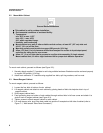
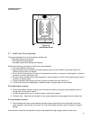
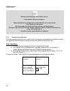
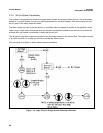
The analyzer uses a batch flow method for automatically analyzing a sample against a fixed standard (refer to block
diagram in Figure 31). That is, the touch of a button starts the microprocessorcontrolled program, calibrates the
analyzer, takes measurements of samples, and reports results directly unattendedfor months at a time.
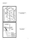
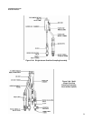
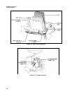
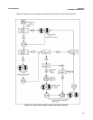
The automated monitoring program determines the sequence for activating each of the valve pumps in the valve
pump assembly to inject air and fluids into the reaction chamber. Each valve pump is associated with a specific
input via the quick disconnect connector on the side of the assembly (the number of reagents is determined by
your particular chemistry and procedure).For example, the inputs for sodium chemistry would be:
• Buffer or Ionic Strength Adjustor, reagent #1
• Sample
• Grab sample
• Baseline
• Standard
• Air
• Evacuation of chamber
• Recirculate
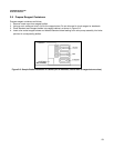
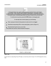
For a multistream system, solenoid valves in the analyzer reagent cabinet open and close streams for sampling.
When sampling, the keypad panel LEDs identify which sample stream (valve number) is associated with the dis
played value, and which valve is now open for sampling. Although the system runs samples on its own, you may
also perform a manual grab sampling or a manual calibration at any time.
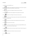
Figure 31. Simple Block Diagram
Valve
Pump
Electronics
Data output
ISE
(ion selective
electrode)
Reaction
Cell
SECTION 3
OPERATING THE ANALYZER