


41
CFA3000 MANUAL SECTION 7
INSTRUMENT DESCRIPTION
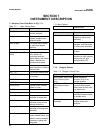
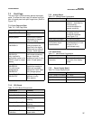
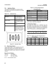
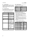
Part Function
Pump Housing Contains and protects
valve pump electronics
Pump Valve pump routes
sample and reagents
through the analyzer
Reagent Barb Fittings Male half of tubing
connector. Tubes are
connected to reagents
and sample
Reaction Vessel
Assembly
Contains reaction cell,
heating block
6position Connector Electrical power to
heating bath
9position Connector Electrical power to pump
LED Green is OK; RED is
Low pressure
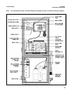
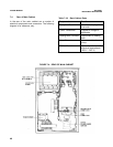
Part Function
Sample and Reagent
Tubing
Colorcoded straws and
labeled tubes for
transport of solutions
“D” Connector Connects to small, 16pin
connector on CPU boards
Vent Line Vents reaction cell to
waste
Pump Drip Tray Catches leaks and
directs them to the leak
detector
LEDS Identify which injector is
active.
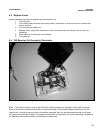
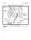
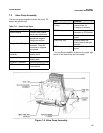
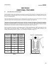
7.5 Valve Pump Assembly
The vacuum pump assembly includes the pump, PC
board, and reaction cell.
Table 7 11: Valve Pump Parts
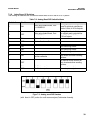
* Vacuum/Pressure LED is located on the upper right
corner of the ValvePump as it is installed
Figure 75. Valve Pump Assembly