


45
CFA3000 MANUAL SECTION 8
ADDIDIONAL FEATURES
SECTION 8
ADDITIONAL FEATURES
8.1 Chart Recorders and Data Loggers
A chart recorder or other data acquisition device may be connected to the analyzer for a permanent record of sam
ple concentration. Setting the output 420 mA 05 Vdc from the keypad panel allows you to adjust 420 mA and 0
5 Vdc to a recording device.
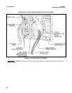
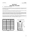
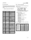
These input devices must be isolated or have a floating ground (not reference to ground). The contacts for recorder
output are located at the input/output panel on the side of the analyzer (see Figure 81).
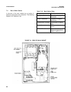
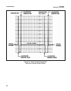
The analyzer will operate normally with data output to the chart recorder or other device. During normal operation,
calibration is performed biweekly. This may vary by Chemistry. To indicate the beginning and end of a calibration
sequence, the recorder makes a quick trace down to zero, and up to full scale. This is called a calibration marker.
After calibration, the recorder resumes recording the sample values (refer to Figure 82).
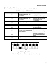
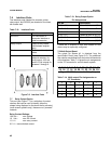
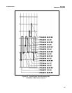
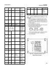
When a recorder is connected to a multistream system, a ”stream identification blip” (SIB) is produced prior to the
output signal for that particular stream. This allows quick identification of individual stream readings on the
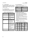
recorder. SIB values are shown in Table 81, and tracings are illustrated in Figure 83.
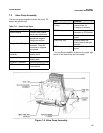
Figure 81. Input/Output Panel
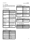
Table 81: Stream Identification Blips
(SIB’s)
Stream #
Voltage
Output
% Scale of
Recording
Marking
1 0.5 10
2 1.0 20
3 1.5 30
4 2.0 40
5 2.5 50
6 3.0 60
Grab 3.5 70