


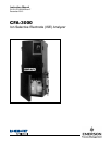

CFA3000 ISE Analyzer TABLE OF CONTENTS
Instruction Manual
1.0 INTRODUCTION...........................................................................................................................1
1.1 Thoroughly Read This Manual......................................................................................................2
1.2 Analyzer Benefits...........................................................................................................................2
1.3 WARNING Electrical Shock Hazard..........................................................................................3
2.0 INSTALLING THE ANALYZER....................................................................................................4
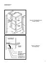
2.1 Unpack Parts .................................................................................................................................4
2.2 Mount Main Cabinet ......................................................................................................................6
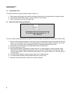
2.3 Mount Reagent Cabinet ................................................................................................................6
2.4 Install Waste Tube .........................................................................................................................8
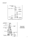
2.5 Mount Overflow Sampling Assembly............................................................................................8
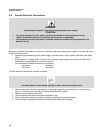
2.6 Prepare Electrical Connections...................................................................................................10
2.7 Install Valve Pump Assembly ......................................................................................................11
2.8 Prepare Reagent Containers ......................................................................................................13
3.0 OPERATING THE ANALYZER..................................................................................................14
3.1 Operational Overview..................................................................................................................14
3.2 Check Sample Stream ................................................................................................................15
3.2.1 Check Fluidics .............................................................................................................................15
3.2.2 Check Reagents..........................................................................................................................15
3.2.3 Turn On Power ............................................................................................................................15
3.2.4 Test Valve Pump Operation ........................................................................................................16
3.2.5 Set Up Stream Parameters ........................................................................................................20
3.3 Set Reagent Supply Time ..........................................................................................................22
3.4 Set Scaling Outputs.....................................................................................................................22
3.4.1 Record mV ................................................................................................................................23
3.4.2 Initiate Auto Calibration ..............................................................................................................23
3.5 Process a Grab Sample .............................................................................................................24
3.6 Manually Sample a Particular Stream .......................................................................................25
3.7 Shutdown ................................................................................................................................25
3.8 Quick Start ................................................................................................................................26
4.0 MAINTAINING THE ANALYZER ...............................................................................................27
4.1 Analyzer Equipment ....................................................................................................................27
5.0 TROUBLESHOOTING PROCEDURES....................................................................................28
5.1 Troubleshooting Chart.................................................................................................................28
5.2 Test Functions .............................................................................................................................29
6.0 REPAIR PROCEDURES............................................................................................................31
6.1 Replace Valve Pump Assembly..................................................................................................31
6.2 Replace Circuit Boards ...............................................................................................................32
6.3 Replace Fuses.............................................................................................................................33
6.4 Replace ISE Components...........................................................................................................33
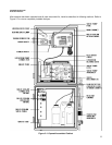
7.0 INSTRUMENT DESCRIPTION ..................................................................................................34
7.1 Analyzer Front View ....................................................................................................................34
7.1.1 Main Cabinet ...............................................................................................................................34
7.1.2 Reagent Cabinet .........................................................................................................................34
7.2 Keypad Panel ..............................................................................................................................36
7.3 Card Cage 41............................................................................................................................37
7.3.1 Card Cage and Door...................................................................................................................37
7.3.2 CPU Board 41............................................................................................................................37
7.3.3 Analog Board...............................................................................................................................37
7.3.4 Valve Board 41............................................................................................................................37
7.3.5 Power Supply Board ...................................................................................................................37
i
CFA3000 ISE Analyzer
TABLE OF CONTENTS