iv
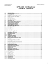
CFA3000 ISE Analyzer TABLE OF CONTENTS
Instruction Manual
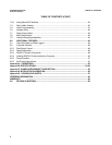
TABLE OF CONTENTS (CON’T)
LIST OF TABLES
Table 51 Troubleshooting Chart.....................................................................................28
Table 52 Test Functions .................................................................................................29
Table 71 Main Cabinet Parts..........................................................................................34
Table 72 Reagent Cabinet Parts....................................................................................34
Table 73 Buttons/LED Functions ...................................................................................36
Table 74 Card Cage Parts .............................................................................................37
Table 75 CPU Board Components.................................................................................37
Table 76 Analog Board Components.............................................................................37
Table 77 Valve Board Components ...............................................................................37
Table 78 Power Supply Board Components..................................................................37
Table 79 Analog Board DIP Switch Positions................................................................39
Table 710 Back Cabinet Parts .........................................................................................40
Table 711 Valve Pump Parts............................................................................................41
Table 712 Interface Ports.................................................................................................42
Table 713 Relay Output Option Pin Assignments............................................................42
Table 714 Multioutput Pin Assignments on “D” Connector.............................................42
Table 715 Overflow Sampling Assembly Parts ................................................................43
Table 81 Stream Identification Blips (SIBs)....................................................................45
Table 82 Normal Data Output Format............................................................................48
Table 83 Data Configuration ..........................................................................................48
Table 84 RS232C Pin Configuration.............................................................................48
Table 85 RS232C Commands ......................................................................................50
Table 86 Printer Port Pin Configuration .........................................................................51
Table E1 Singlestream Keypad Help Sheet.............................................................5859
Table E2 Multistream Keypad Help Sheet ...............................................................6062
Table E3 Replacement Parts .........………..……………………………………….…….63


