


3
1.2 Appearance and Part Names
1.2 Appearance and Part Names
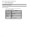
This section gives the names of all parts of the emulator unit.
■ Appearance and Part Names
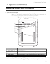
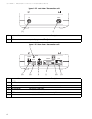
Figure 1.2-1 "Top view of the emulator unit" to Figure 1.2-3 "Rear view of the emulator unit"
show the exterior of the emulator unit and give the names of all of its parts.
Figure 1.2-1 Top view of the emulator unit
No. Name Description
(1) Status indicator LCD
Displays different kinds of information, including setting values, communication status,
and operating status.
(*1)
(2) POWER LED Goes on when emulator power is supplied.
(3) UVCC LED Goes on when user system power (UV
CC
) is supplied.
(*2)
(4) Setting switches Used to change settings and the information displayed on the status indicator LCD.
(*1)
(5) Adapter board connector Connects to an adapter board (option).
*1: For information on the type of information displayed on the status indicator LCD and how to use the setting
switches, see Section
3.7
"Using the Setting Switches."
*2: If the evaluation MCU has a dual source power supply, this LED goes on when both power supplies are turned on.
(1)
(2)
(3)
(4)
(5)
POWER UVCC
MB2147-01
F
2
MC-16 SERIES EMULATOR