


Filename [DR-M1EK_06Name.fm]
Masterpage:Left+
Page 18 August 15, 2003 7:53 pm
INSTALLING YOUR NEW UNIT (cont.)
18
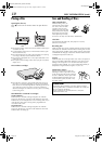
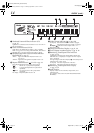
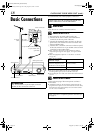
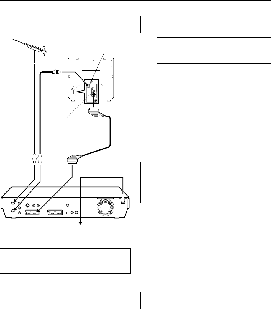
Basic Connections
It’s essential that your unit be properly connected.
A
Install the unit.
Place the unit on a stable, horizontal surface.
B
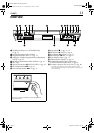
Connect the unit to a TV.
A
Disconnect the TV aerial cable from the TV.
B
Connect the TV aerial cable to the ANTENNA IN
connector on the rear panel of the unit.
C
Connect the ANTENNA OUT connector on the rear
panel of the unit and the TV’s aerial connector with
the provided RF cable.
D
Connect the L-1 IN/OUT connector on the rear panel
of the unit and the TV’s 21-pin SCART connector with
a provided 21-pin SCART cable.
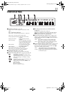
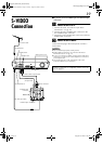
●
The L-1 IN/OUT connector accepts and delivers either a
composite signal (regular video signal), Y/C signal or RGB
signal.
●
Select an appropriate option of “L-1 OUTPUT” as follows
(
੬
pg. 84):
●
Set your TV to the VIDEO (or AV), Y/C, or RGB mode
according to the type of your TV’s SCART connector.
●
For switching the TV’s mode, refer to the instruction manual of
your TV.
C
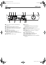
Connect the unit to mains.
Connect the AC plug of the mains power cord into a
mains outlet.
●
“LOADING” blinks on the front display panel when the AC
plug of the mains power cord is connected into a mains outlet,
and it takes the unit approximately 50 seconds to be turned
on. This is not a malfunction.
A
TTENTION:
Your TV must have a 21-pin AV input connector
(SCART) for the connection to the unit.
Back of TV
21-pin SCART connector
TV aerial
cable
RF cable
(provided)
21-pin SCART cable
(provided)
Mains power cord
Mains outlet
Back of unit
L-1 IN/OUT
ANTENNA IN
ANTENNA OUT
Aerial connector
THESE STEPS MUST BE COMPLETED BEFORE ANY
VIDEO OPERATION CAN BE PERFORMED.
When your TV’s SCART
connector accepts:
Set “L-1 OUTPUT” to:
Y/C signal (separated
luminance (brightness) and
chrominance (colour) signals)
“SCART S-VIDEO”
RGB signal “SCART RGB”
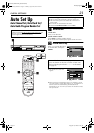
After connection is completed, perform “Auto Set Up”
on page 21.
DR-M1EK_01.book Page 18 Friday, August 15, 2003 7:53 PM