23
PROG
0
123456789
The actual volume will be determined by summing the
value of the changes produced by the amp EG with the val-
ues of Alternate Modulation etc., and if the levels of the amp
EG are low, the modulation applied by Alternate Modula-
tion will also be less.
For example if you set “AMS” to Pedal #04 and set Global 0–
3a “Foot Pedal Assign” to Foot Pedal (CC#04), positive (+)
settings of this parameter will make the volume increase
when you advance a foot pedal connected to the ASSIGN-
ABLE PEDAL jack. However if the volume is already at the
maximum because of the EG settings etc., it cannot be
increased any farther. With negative (–) settings of this
parameter, advancing the pedal will decrease the volume.
AMS (LFO1 AMS)
[Off, (PEG, FEG, AEG, KT, EXT)]
Indicates the source that will control the depth by which
“OSC1 LFO1” (3–1) will modulate the volume of oscillator 1
(☞p.152 “AMS List”).
Int. (AMS Intensity) [–99…+99]
Specifies the depth and direction of the effect that “OSC1
LFO1” will have on the volume of oscillator 1. Negative (–)
values will invert the LFO waveform.
AMS (LFO2 AMS)
[Off, (PEG, FEG, AEG, KT, EXT)]
Indicates the source that will control the depth by which
“OSC1 LFO2” (3–2) will modulate the volume of oscillator 1
(☞p.152 “AMS List”).
Int. (AMS Intensity) [–99…+99]
Specifies the depth and direction of the effect that “OSC1
LFO2” will have on the volume of oscillator 1. Negative (–)
values will invert the LFO waveform.
■ 6–2: UTILITY
☞“Write Program” (0–1), “Copy Oscillator,” “Swap Oscilla-
tor” (1–1)
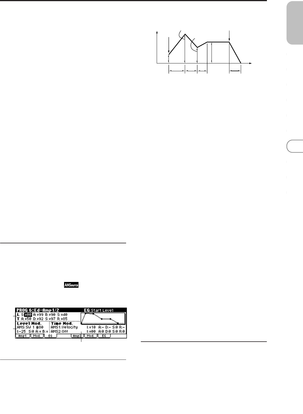
6–3: EG (Amp1 EG)
Indicates settings to specify how Amp 1 will cause the vol-
ume of oscillator 1 to change over time.
6–3a: Amp1 EG
These parameters specify how the amp 1 EG will change
over time.
L (Level parameters):
S (Start Level) [00…99]
Specifies the volume level at note-on.
If you want the note to begin at a loud level, set this to a high
value.
A (Attack Level) [00…99]
Specifies the volume level that will be reached after the
attack time has elapsed.
B (Break Point Level) [00…99]
Specifies the volume level that will be reached after the
decay time has elapsed.
S (Sustain Level) [00…99]
Specifies the volume level that will be maintained from after
the slope time has elapsed until note-off occurs.
T (Time parameters):
A (Attack Time) [00…99]
Specifies the time over which the volume will change after
note-on until it reaches the attack level.
If the start level is 0, this will be the rise time of the sound.
D (Decay Time) [00…99]
Specifies the time over which the volume will change from
when it reaches the attack level until it reaches the break
point level.
S (Slope Time) [00…99]
Specifies the time over which the volume will change from
when it reaches the break point level until it reaches the sus-
tain level.
R (Release Time) [00…99]
Specifies the time over which the volume will change after
note-off until it reaches 0.
6–3b: Level Mod. (Level Modulation)
These parameters let you use AMS to modulate the amp 1
EG levels that were specified in “Amp 1 EG” (6–3a).
AMS (Level Mod. AMS) [Off, (KT, EXT)]
Selects the source that will control the “Level” parameters of
the amp 1 EG (☞p.152 “AMS List”).
I (AMS Intensity) [–99…+99]
Specifies the depth and direction of the effect that “AMS
(Level Mod. AMS)” will have.
For example, if “AMS (Level Mod. AMS)” is Velocity, setting
“S (AMS SW Start),” “A (AMS SW Attack),” and “B (AMS
SW Break)” to + and setting “Intensity” to a positive (+)
6–3a
6–3b
6–3c
Note-on
Note-off
Attack
Time
Decay
Time
Release Time
Attack Level
Sustain
Level
Time
Break Point
Start
Level
Slope
Time
Amplifier EG
Volume


