


41
••••••••••••••••••••••••••••••••••••••••••••••••••••••••••••••••••••••••••••••••••••••••••••••••••••••••••••••••••••••••••••
Operations
ENGLISH
<RECORD SETTINGS>
■ Settings concerning normal recording and
alarm recording
This unit allows independent settings for normal recording
and alarm recording. By this, more detailed settings are
possible such as changing the recording intervals of the
camera inputting the alarm signals while maintaining the
normal recording settings as they are.
Certain settings and mode changes are limited
during Alarm recording. Pressing the ALARM INTER-
RUPT button halts additional alarm inputs, and lifts
the limitations by stopping recording.
During recording, the setting in the <RECORD
SETTING> screen cannot be changed.
When the cameras for recording are not input
video signal, warning display of “NO SIGNAL” ap-
pears (for details,
see “Warnings and CALL
OUT output” pages 87,88).
■ Recording mode settings for normal
recording and alarm recording
Setting of the camera number for alarm recording and
emergency recording, the TRIGGER for alarm recording,
the recording intervals and recording picture quality for nor-
mal recording and alarm recording and whether to perform
pre-alarm recording for alarm recording can be set here
(for normal recording, see “Basic manual recording”
pages 21-23). Pre-alarm recording is a function to start re-
cording before the ALARM IN terminal on the rear of the
unit is grounded or motion is detected (for details concern-
ing pre-alarm recording, see page 64).
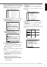
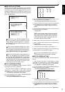
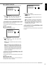
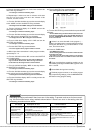
<RECORD SETTINGS>
>>
ALARM SETTING
RECORD SETTING
ALARM REC DURATION 5S
PRE ALARM REC ( S ) S
MOTION DET REC ALARM
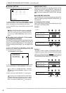
1. Press the SET UP button
}
<SETTINGS>
}
Select “ALARM
SETTING” in the <RECORD SETTINGS> screen and turn the
SHUTTLE ring clockwise.
• The <ALARM SETTING> screen appears.
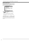
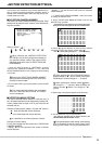
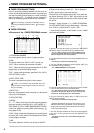
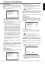
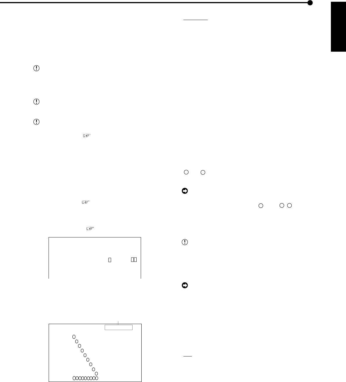
<ALARM SETTING>
>>
ALARM CH
ALARM RECORD CAMERA TRIGGER
1 -------- EXT
2 - ------- EXT
3 -- ------ EXT
4 --- ----- EXT
5 ---- ---- EXT
6 ----- --- EXT
7 ------ -- EXT
8 ------- - EXT
9 -------- EXT
EMR
9
7
4
5
6
1
2
3
8
9
7
4
5
6
1
2
3
8
<ALARM SETTING>
Camera selection during alarm recording
2. (When setting the camera selection during alarm recording
• • • )
Turn the JOG dial and move the cursor to camera selection
item for alarm recording and turn the SHUTTLE ring clockwise.
• The background of setting turns red and flashes.
• Setting ( default : “ALARM CH” )
“ALARM CH” : Alarm recording is performed for only the
cameras set for alarm recording and inputted with alarm
signals. When there is input of alarm signals from multiple
cameras, alarm recording is performed for all cameras
containing alarm signals.
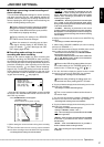
“ALARM PLUS” : Recording is performed in the frame speed
set in “A-PPS” for the camera inputted with alarm signals
during normal recording. All other cameras will be recording
in the normal frame intervals.
“ALARM25” : Recording is performed so that normal
recording and alarm recording each are up to max. 25 frames.
With playback of a recording where an alarm recording has
occurred during normal recording, there will be no recording
interval display.
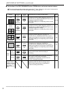
3. Display the desired item to set and turn the SHUTTLE ring
clockwise.
• The setting is confirmed and flashing stops.
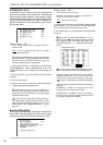
4. (When setting “RECORD CAMERA” (the alarm recording
camera) and “TRIGGER” • • • )
Turn the JOG dial to select the desired “ALARM” (alarm sensor
input number) and turn the SHUTTLE ring clockwise.
• The first item from the left side in the “RECORD CAMERA”
setting display reverses in color.
• The camera numbers are lined in order of the number from
“
1
” to “
9
”. Multiple camera numbers can be selected for
one alarm camera channel number.
When turn the JOG dial counterclockwise, the cam-
era number setting or the TRIGGER setting will re-
verses in color in order such as
1
, EXT,
9
,
8
• • • .
5. Turn the JOG dial to display the desired camera number
reversed in color and turn the SHUTTLE ring clockwise.
• The background of setting turns red and flashes.
While the setting is flashing, the setting screen can-
not be exited even when pressing the SET UP button.
6. Turn the JOG dial to display the desired setting and turn the
SHUTTLE ring clockwise.
• The setting is confirmed and flashing stops.
Two or more camera numbers can be chosen to
one sensor input.
7. Turn the JOG dial clockwise to display “TRIGGER” setting
reversed in color and turn the SHUTTLE ring clockwise.
• The background of setting turns red and flashes.
8. Turn the JOG dial to display the desired setting and turn the
SHUTTLE ring clockwise.
• The setting is confirmed and flashing stops.
• Setting of “TRIGGER” ( default : “EXT” )
“EXT” : Alarm recording can only be started when the ALARM
IN terminal is grounded.
“MD&EXT” : Alarm recording can be started when the ALARM
IN terminal is grounded and the motion is detected
simultaneously.
“MD/EXT” : When the ALARM IN terminal is grounded or
motion is detected alarm recording is started.
“MD” : Alarm recording can only be started when the motion
is detected.