


52
••••••••••••••••••••••••••••••••••••••••••••••••••••••••••••••••••••••••••••••••••••••••••••••••••••••••••••••••••••••••••••••••••••••••••••
• SETTINGS
RS-232C settings can be made when setting “MODE”
previous to “REMOTE A”, “REMOTE B” or “REMOTE C”.
Perform settings so that the settings are the same
with the connecting PC.
Setting of “TRANSMISSION MODE” ( default : “9600” )
“1200”, “2400”, “4800”, “9600”, “19200”
Setting of “DATA BIT LENGTH” ( default : “8BIT” )
“8BIT”, “7BIT”
Setting of “PARITY BIT” ( default : “NONE” )
“NONE”, “ODD”, “EVEN”
Setting of “STOP BIT LENGTH” ( default : “1BIT” )
“1BIT”, “2BIT”
Setting of “DELIMITER” ( default : “CR” )
“CR”, “CR•LF”
1. Set “MODE” in the <RS-232C> screen to “REMOTE A”,
“REMOTE B” or “REMOTE C”.
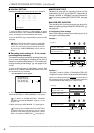
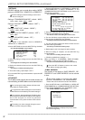
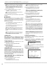
2. Select “SETTINGS” and turn the SHUTTLE ring clockwise.
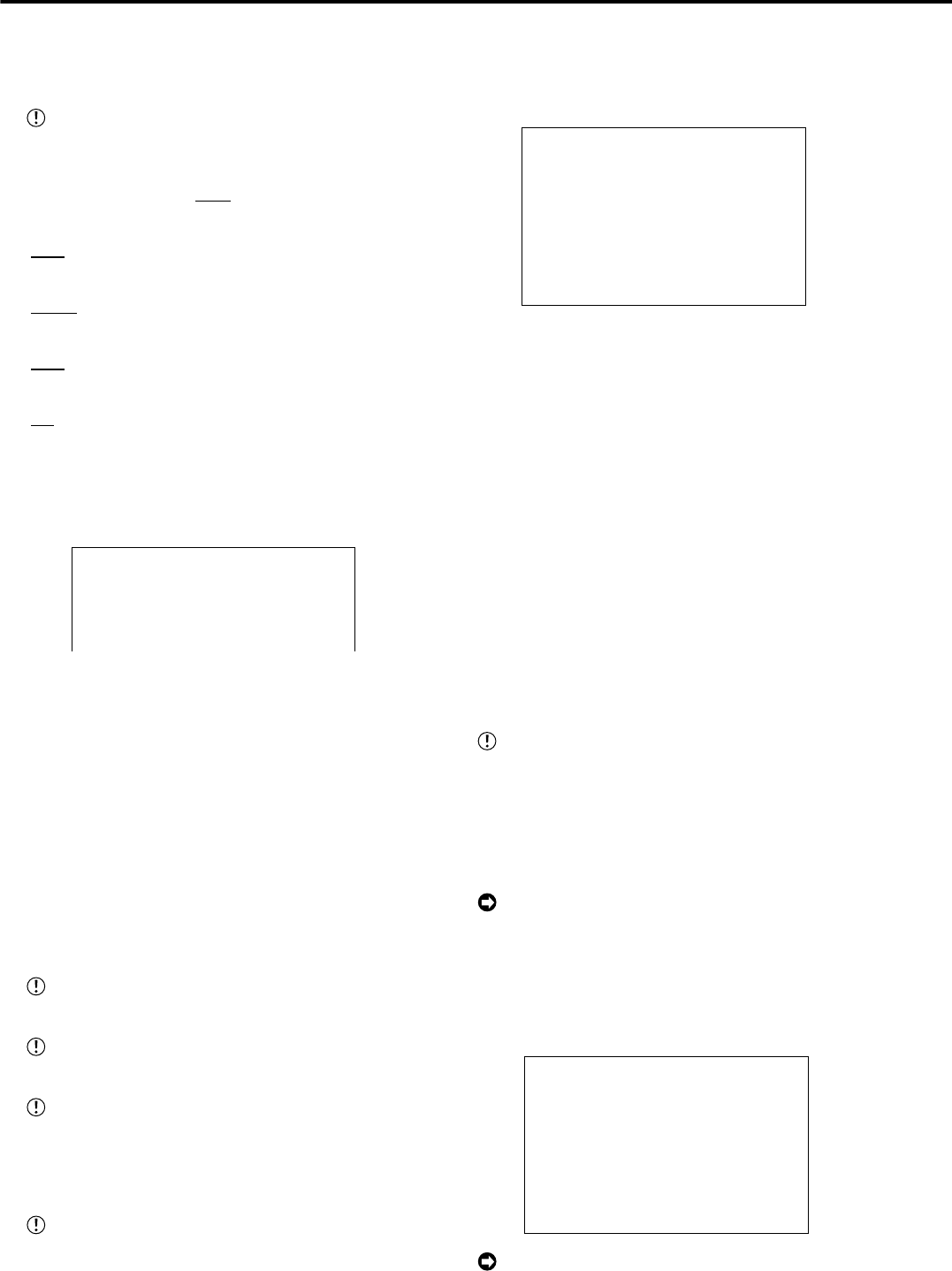
• The <RS-232C SETTINGS> screen appears.
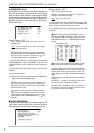
<RS-232C SETTINGS>
>>
TRANSMISSION MODE 9600
DATA BIT LENGTH 8BIT
PARITY BIT NONE
STOP BIT LENGTH 1BIT
DELIMITER CR
3. Select the setting to change and turn the SHUTTLE ring
clockwise.
• The background of the setting turns red and flashes.
4. Display the desired sub item and turn the SHUTTLE ring
clockwise.
• The setting is confirmed and flashing stops.
5. To set other setting, repeat steps 3 and 4.
6. Turn the SHUTTLE ring counterclockwise or press the SET
UP button.
♦ ETHERNET
The IP address used to specify the connected recorder, sub
net mask setting, and MAC address can be referred to here.
Do not change the setting without sufficient knowl-
edge about the network setting.
In regard to the network settings it is recommended
to obtain advance confirmation by the network manager.
Do not assign “000.000.000.000” IP address. And
do not assign it as the broadcast address. If this address
were to be assigned, we could not guarantee
communications or any other functions of the recorder
unit.
The setting can not be changed during the record.
Stop the record to change the setting.
1. Press the SET UP button
}
<SETTINGS>
}
<INITIAL SET
UP/INFORMATION>
}
Select “ETHERNET” in the
<COMMUNICATION PORT SETTINGS> screen and turn the
SHUTTLE ring clockwise.
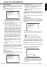
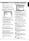
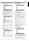
• The <ETHERNET> screen appears.
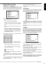
<ETHERNET>
>>
IP ADDRESS 192.168.000.100
SUB NET MASK 255.255.255.000
GATEWAY 000.000.000.000
E-MAIL ADDRESS
SERVICE PORT SETTING
ALARM NOTIFICATION SETTING
<MAC ADDRESS>
08-00-70-2E-3F-FF
PLEASE PRESS SET UP BUTTON
TO APPLY NEW SETTING
2. Select the setting you wish to alter by turning the JOG dial
and then turn the SHUTTLE ring clockwise.
• The leftmost number of the setting will reverse in color.
3. Turn the JOG dial to reverse display the number you wish
to alter and turn the SHUTTLE ring clockwise.
• The background of the selected number turns red and flashes.
4. Turn the JOG dial to display the desired number and turn
the SHUTTLE ring clockwise.
• The setting is confirmed and flashing stops.
5. Repeat steps 2 and 4 to change the other numbers.
6. When the setting is complete, turn the SHUTTLE ring
counterclockwise.
• The cursor move to setting directly to the left.
7. (Finalizing updated menu settings • • • )
When any setting of “IP ADDRESS”, “SUB NET MASK”,
“GATEWAY” is changed, press ths SET UP button.
• The power turns off automatically, then the unit will boot up.
Press the SET UP button to return to the normal
screen without changing the setting.
• E-MAIL ADDRESS
The contents of the setting of “SMTP SERVER”, “RE-
CORDER ID” and “USER ADDRESS” can be referred
to here.
The specific software is required to input “SMTP
SERVER”, “RECORDER ID” and “USER ADDRESS”.
Please refer to the instruction manual of the software.
1. Press the SET UP button
}
<SETTINGS>
}
<INITIAL SET
UP/INFORMATION>
}
<COMMUNICATION PORT SETTING>
}
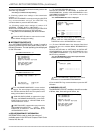
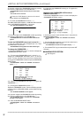
select “E-MAIL ADDRESS” in the <ETHERNET> screen.
• The <E-MAIL ADDRESS> screen appears.
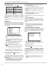
<E-MAIL ADDRESS>
SMTP SERVER
RECORDER ID
USER ADDRESS
1
2
3
4
5
“USER ADDRESS” is displayed only for 20 charac-
ters from the beginning.
<INITIAL SET UP/INFORMATION> (continued)