


7
RQT7394
Getting started
≥The equipment connections described are examples.
≥Before connection, turn off all equipment and read the appropriate operating instructions.
≥Peripheral equipment and optional cables sold separately unless otherwise indicated.
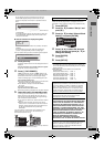
The connection will allow the video cassette recorder to be used for playback when this unit is turned off. For optimum operation, it is
recommended that this unit be connected as shown below.
A to R are indexes for Spanish Quick Reference.
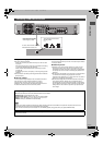
∫ The unit’s RF OUT terminal
The picture and sound signal from this unit does not go through the
RF OUT terminal to the television.
Make sure you connect one of the following terminals on this unit to
the television: the AUDIO/VIDEO OUT terminal, the S-VIDEO OUT
terminal or the COMPONENT VIDEO OUT terminal. If the
television has none of these terminals, consult your local dealer.
≥Refer to page 9 if the antenna connector doesn’t match.
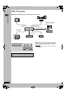
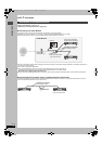
Do not connect the unit through a video cassette recorder
Video signals fed through video cassette recorders will be affected
by copyright protection systems and the picture will not be shown
correctly on the television.
≥When connecting to a television with a built in VCR, connect to
the input terminals on the television side, not the VCR side.
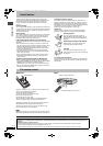
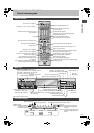
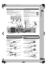
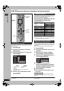
Connection with a television and video cassette recorder
YPB PR
R - AUDIO - L
VIDEO
S-VIDEO
OPTICAL
G-LINK
COMPONENT
VIDEO OUT
(480p/480i)
DIGITAL AUDIO OUT
(PCM/BITSTREAM)
IN1 (L1)
IN3 (L3)
R - AUDIO - L
VIDEO
S-VIDEO
OUT1 OUT2
VHF/UHF
RF IN
RF OUT
SUB WOOFER
CENTER
RL
FRONT
AUDIO OUT
jLAN (10/100)
5.1ch
R - SURROUND - L
VHF/UHF
RF IN
VHF/UHF
RF OUT
AUDIO
R
AUDIO
L
VIDEO
IN
AUDIO
R
AUDIO
L
VIDEO
OUT
OUTIN
VHF/UHF
RF IN
COMPONENT
VIDEO IN
AUDIO IN
R L
S VIDEO IN
VIDEO IN
D Cable from wall or antenna signal
B Television
P To household AC outlet
(AC 120 V, 60 Hz)
G Video cassette recorder
N Cooling fan
O AC power supply cord
Connect only after all other
connections are complete.
K This unit
J Audio/Video cable
E Splitter
indicates included accessories.
indicates accessories not included.
M To IN1 (L1)
C When connecting using these terminals, ensure
you connect the audio cables to the corresponding
audio input terminals on the television.
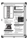
R
S-VIDEO OUT terminal
Connect to S-VIDEO IN terminal on the television through
a S-Video cable.
The S-VIDEO OUT terminal achieves a more vivid picture
than the VIDEO OUT terminal. (Actual results depend on
the television.)
Q
COMPONENT VIDEO OUT terminal
Connect to COMPONENT VIDEO IN terminals on
the television through a component video cable.
These terminals can be used for either interlace or
progressive output (➡ page 69) and provide a purer
picture than the S-VIDEO OUT terminal.
≥Connect to terminals of the same color.
H 75 ≠ coaxial cable
A
I Yell ow
White
Red
F
Red White Yellow
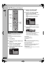
L To OUT1 or OUT2
J Audio/Video cable
H 75 ≠ coaxial cable
F
Red White Yellow
F
Red White Yellow
B Television B Television
K This unit
G VCR
G VCR
K This unit
新セットアップ .fm 7 ページ 2004年7月20日 火曜日 午後7時28分