


Chapter 1 Overview
14 Chapter 1 Overview
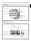
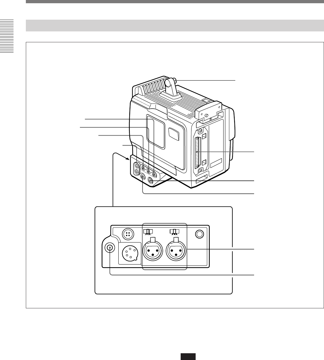
DC OUT
12V
DC IN
LINE MIC
+48V ON
CH-1 AUDIO IN CH-2
TALLY
LINE MIC
+48V ON
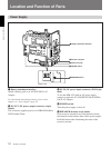
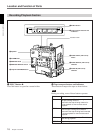
Input/Output Connectors
Location and Function of Parts
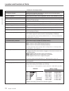
1 TC OUT (time code output) connector (BNC)
This outputs time code signals from the built-in time
code generator. When a time code signal is input to the
TC IN connector 2, this output signal is synchronized
to it.
For details about time code, see “Setting Time Code Value”
on page 51.
2 TC IN (time code input) connector (BNC)
Input an external signal for synchronizing the built-in
time code generator. Use an SMPTE (DSR-1) or EBU
(DSR-1P) time code signal.
Note
Use a jitterless LTC signal. Using an LTC signal
reproduced by other equipment may cause the DSR-1/
1P to malfunction.
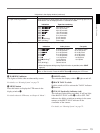
3 GEN LOCK IN connector
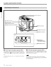
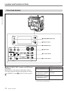
Rear
Shoulder strap fitting
4 AUDIO OUT CH-1/CH-2 connectors
1 TC OUT connector
8AUDIO IN CH-1/
CH-2 connectors and
input selection switches
9 EARPHONE connector
5 Camera connector
6 S VIDEO OUT connector
7 VIDEO OUT connector
2 TC IN connector