


Chapter 2 Fitting and Connecting Related Equipment
30 Chapter 2 Fitting and Connecting Related Equipment
LINE MIC
+48V ON
AUDIO IN
CAM
REAR
CH-1 CH-2
LINE MIC
+48V ON
AUDIO IN
CAM
REAR
CH-1 CH-2
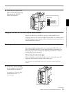
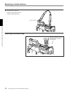
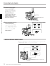
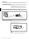
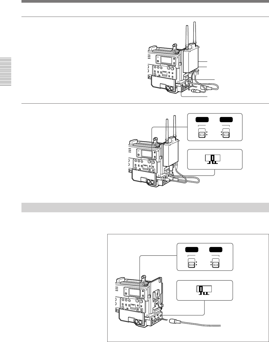
3 Connect an optional output
cable into the OUTPUT
connectors on the BTA-801
and either of the AUDIO IN
CH-1/CH-2 connectors.
Connect the DC power
(supplied with the BTA-801)
cable into the DC 12V IN
connector on the BTA-801 and
the DC OUT connector.
4 Set the AUDIO IN (CH-1/CH-
2) switch (for the tuner-
connected channel) to REAR
and the input selection switch
for the AUDIO IN CH-1/CH-2
connector (where the tuner
cable is connected) to MIC
(center position).
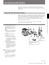
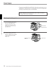
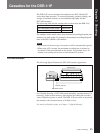
Connecting Audio System
Using an External Audio System
Connect an audio mixer or other external audio system component to the
AUDIO IN CH-1/CH-2 connector as shown below.
Input selection switch: Set to MIC.
AUDIO IN (CH-1/CH-2) switch: Set to REAR.
OUTPUT
DC 12V IN
AUDIO IN CH-1/CH-2
DC OUT
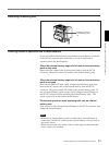
Input selection switch: Set to LINE.
AUDIO IN (CH-1/CH-2) switch: Set to REAR.
To audio mixer, etc.
AUDIO IN
CH-1/CH-2