


Chapter 1 Overview
Chapter 1 Overview 15
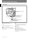
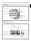
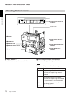
3 GEN LOCK IN (gen lock video input) connector
(BNC)
When synchronizing the camera to an external signal,
input a reference video signal (VBS or BS).
4 AUDIO OUT CH-1/CH-2 connectors (phono
jacks)
These output the sound being recorded or played back.
Connect to a stereo amplifier or video monitor’s audio
input connectors.
5 Camera connector (PRO 76-pin DIGITAL or
PRO 50-pin)
Connect to the camera’s VTR connector. Two types of
connectors are provided and can be replaced according
to the camera.
PRO 76-pin DIGITAL: For connecting to the DXC-
D30/D30P/D35/D35P digital video camera.
PRO 50-pin: For connecting to the DXC-327B/537A/
637A (or DXC-327BP/537AP/637AP) series
analog video camera.
For details on replacing camera connectors, see “Mounting
on Video Camera” (page 24).
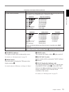
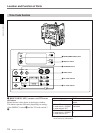
6 S VIDEO OUT (S-video output) connector (DIN
4-pin)
This outputs the image being shot or played back as S-
video signals. Connect to the S-video input connector
on a VCR or video monitor.
Note
When the CA-514/514P Camera Adaptor is connected,
only playback audio is output from this connector.
7 VIDEO OUT (composite video output)
connector (BNC)
This outputs the image being shot or played back as
composite video signals. Connect to the video input
connector on a VCR or video monitor.
Notes
• The output signal from this connector may
discontinue when switching the operation between
recording and playback. Do not use as a reference
signal for external equipment.
• When the CA-514/514P Camera Adaptor is
connected, only playback audio is output from this
connector.
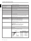
8 AUDIO IN CH-1/CH-2 (audio input channel 1
and 2) connectors (XLR 3-pin, female) and input
selection switches
Connect a microphone or other external audio
equipment. Set the input selection switches as shown
below according to the microphone or equipment.
MIC +48V ON (right position): For connecting to a
48-V microphone
Note
If this position is selected for a microphone other
than 48-V microphone, the microphone may be
damaged.
MIC (center position): For connecting any
microphone other than 48-V microphone
LINE (left position): For connecting an external audio
signal source such as a stereo amplifier.
9 EARPHONE connector (mini-jack)
Connect an earphone or headphones. This outputs the
sound which was output to the speaker, but mutes the
speaker.