


66
APPENDIX
APPENDIX
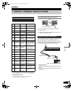
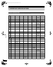
1. CONTROL TERMINAL SPECIFICATIONS
*1 Used for twisted-pair cable connection.
*2 Outputs SERIES REC OUT when OVER WRITE in REC MODE SET is
“OFF”, and SERIES REC is “-1M”, “-2M”, or “-3M”. Outputs NON REC
OUT when SERIES REC is “OFF”.
*3 The following warnings are output:
z Hard disk drive error z Fan error z Recording error
z No input signal when VIDEO LOSS is ON.
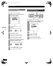
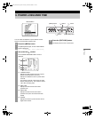
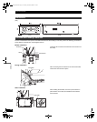
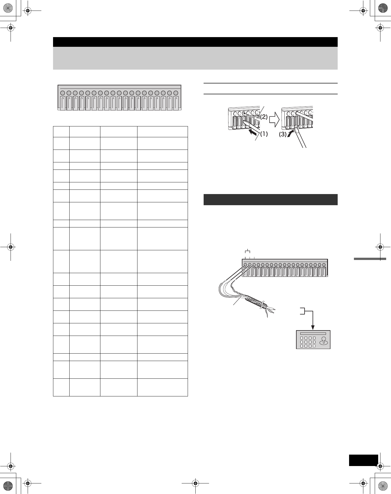
Connecting cables to the control terminals
(1) Push in the lock pin with a flat-blade screwdriver.
(2) Insert the cable.
(3) Pull out the lock pin with a flat-blade screwdriver. The
cable is now secured in place.
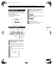
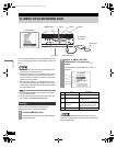
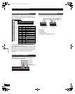
The connections for a system controller are shown below.
Insert a twisted-pair cable (sold separately) into the
RS-485A, RS-485B and C (ground) terminals on the rear
panel. Connect the RS-485A and RS-485B output to signal
A and signal B respectively of the system controller.
z Twisted-pair cable
Reduces signal interference caused by noise from other
cables.
z For information about the system controller, contact your
local dealer.
Terminal
No.
Name Signal Function
1 RS-485A RS-485
To RS-485 terminal signal
A*
1
2 RS-485B RS-485
To RS-485 terminal signal
B*
1
3 C Common
4REMOTE
Resistance ladder
connection
Remote Control terminal
5 C Common
6CLOCK ADJ IN
Normal open,
Low level active
Input for clock setting
7
CLOCK ADJ
OUT
Normal resistance
5V DC/57kΩ,
Low level active
Output for clock setting
8 C Common
9
SERIES REC
IN
Normal open,
Low level active
Input terminal used when
recording with multiple
digital video recorders
connected.
10
NON REC
OUT/SERIES
REC OUT
Normal resistance
5V DC/57kΩ,
Low level active
Output terminal used
when recording with
multiple digital video
recorders connected.*
2
11 ALARM IN 1
Normal open,
Low level active
Alarm input for channel 1
12 ALARM IN 2
Normal open,
Low level active
Alarm input for channel 2
13 ALARM IN 3
Normal open,
Low level active
Alarm input for channel 3
14 ALARM IN 4
Normal open,
Low level active
Alarm input for channel 4
15
ALARM
RESET
Normal open,
Low level active
Alarm reset input
16 ALARM OUT
Normal resistance
5V DC/57kΩ,
Low level active
ALARM OUT
17 C Common
18
WARNING
OUT
Open collector
(500 mA),
Low level active
Warning output*3
19
DISK FULL
OUT
Open collector
(500 mA),
Low level active
Recording area full
warning
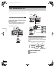
123456789
10 11 12 13 14 15 16 17 18 19
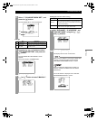
System controller connections
Cable
Flat-blade screwdriver
123456789
10 11 12 13 14 15 16 17 18 19
RS-485
ABC
Twisted-pair cable
Ground
To signal B
To signal A
RS-485
terminal
System controller (sold separately)
e00_VDH_M814.book Page 66 Thursday, October 28, 2004 9:59 AM