


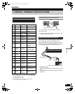
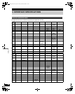
CONTROL TERMINAL SPECIFICATIONS
67
APPENDIX
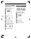
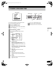
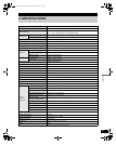
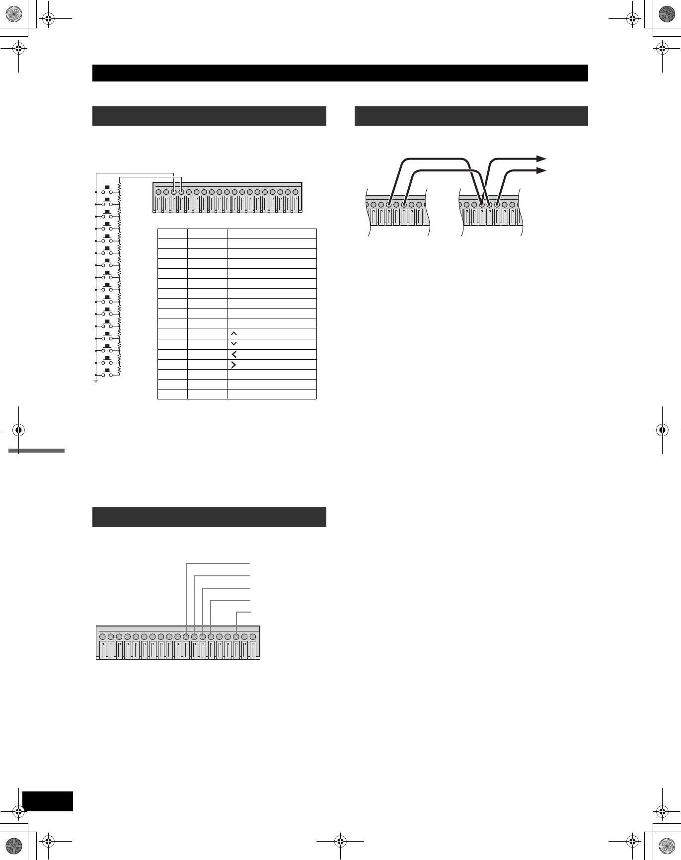
The connections for a remote control circuit are shown
below. Connect the remote control to the REMOTE terminal
and C (ground) terminal.
Use a resistance of 1/10 ohms or more and with a D
ranking (precision 0.5% or finer).
SW16 operates the same as the [REC/STOP] button on the
digital video recorder. When the switch is turned on while
not recording, recording begins. When the switch is kept on
for 2 seconds or more while recording, recording is
stopped.
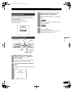
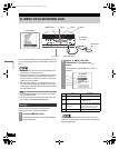
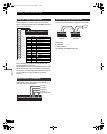
Alarm sensors can be connected to the ALARM IN 1 to 4
terminals and C (ground) terminal.
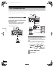
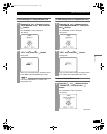
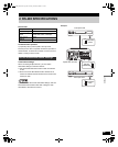
Connect the control terminals by cables as shown below.
Terminal No.
8: COMMON
9: SERIES REC IN
10: NON REC OUT/SERIES REC OUT
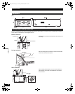
Remote control connections
Alarm sensor connections
123456789
10 11 12 13 14 15 16 17 18 19
220
220
300
360
470
680
820
1.2k
1.8k
2.2k
3.3k
4.7k
7.5k
13k
27k
68k
SW 1
SW 2
SW 3
SW 4
SW 5
SW 6
SW 7
SW 8
SW 9
SW 10
SW 11
SW 12
SW 13
SW 14
SW 15
SW 16
Key Resistance Corresponding button
SW1 220 Ω CHANNEL button 1
SW2 440 Ω CHANNEL button 2
SW3 740 Ω CHANNEL button 3
SW4 1100 Ω CHANNEL button 4
SW5 1570 Ω QUAD/SEQUENCE
SW6 2250 Ω AUDIO
SW7 3070 Ω SEARCH
SW8 4270 Ω MENU
SW9 6070 Ω EXIT/OSD
SW10 8270 Ω
SW11 11570 Ω
SW12 16270 Ω (REVIEW)
SW13 23770 Ω (CUE)
SW14 36770 Ω STILL
SW15 63770 Ω PLAY/STOP
SW16 70570 Ω REC/STOP
123456789
10 11 12 13 14 15 16 17 18 19
T
o sensor
1
To sensor 2
To sensor 3
To sensor 4
C (ground) terminal
Series recording connections
56789
10 11 12 13
56789
10 11 12 13
2nd DVR
1st DVR
To 3rd
DVR
e00_VDH_M814.book Page 67 Thursday, October 28, 2004 9:59 AM