


11
4 INSTALLATION
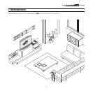
POSITIONING THE TWO UNITS
The HTL40 LINK system consists of two separate units (the DigiOp
-
tic™ Image Processor and the screen), each of which is equipped
with a power cable; the two units are interconnected by a 20 m
fibre optic cable.
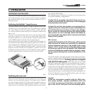
Positioning the DigiOptic™ Image Processor
The ideal location for the DigiOptic™ Image Processor is on a cabi
-
net shelf or on a rack (dimensions are compatible with a standard
19” rack). Make sure that the support surface is stable and that
the unit has sufficient space around it for ventilation purposes (at
least 3 cm).
The unit is connected to the mains via an external power supply
unit with an output of +7 Vdc; the unit’s main power switch is on
the power supply unit. Connect the power supply unit output cable
to the POWER socket located on the rear panel (Fig. 2).
Use exclusively the power supply unit provided with the system or
an alternative power supply unit expressly approved by SIM2. For
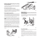
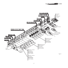
rack mounting of the DigiOptic™ Image Processor use the screws
and LH / RH supports supplied with the product. Undo the screws
fixing the cover to the base of the DigiOptic™, position the LH and
RH supports and secure them to the unit with the screws supplied.
Use the supplied screws to secure the unit to the rack (Fig.6).
DIGIOPTIC ™ IMAGE P
ROCESSOR
OFF
ON
Fig.6
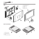
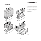
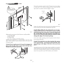
Positioning the screen unit
Some minor assembly steps must be carried out on the screen unit
before it can be positioned correctly. The display can be installed
on a wall, using the specific VESA rails and the supplied screws, or
placed on a table using the supporting base (optional - For further
requirements or information concerning the support base contact
your nearest SIM2 dealer).
The following section describes the operations to be performed for
the various installation configurations.
Caution! All the operations described below must be ex
-
ecuted exclusively with the mains power cable unplugged
from the mains socket outlet.
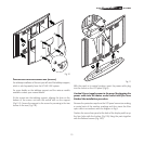
Caution! Do not place the wooden rear panel against ir
-
regular surfaces or surfaces that anyway could damage the
panel. Protect the rear panel from scoring or other damage.
Do not scratch the rear panel by means of rubbing against
other surfaces or score it through contact with sharp ob-
jects. Do not place any objects on the rear panel and avoid
laying it flat if possible.
W
ALL MOUNTING
Caution! Wall mounting of the LCD screen calls for special
skills and must be carried out exclusively by authorised,
trained technicians. Because of the weight of the screen
(approx. 345 N, 35 kg) wall mounting operations should
be carried out with at least two people. Sim2 Multimedia
declines all liability for possible injury to persons or dam-
age to property deriving from incorrect installation of the
screen.
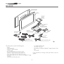
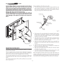
Fixing of the display to the wall is performed by means of an attach
-
ment in compliance with VESA FDMITM standards (VESA Flat Display
Mounting Interface Standard). The fixing system is not supplied
with the HTL40 LINK system. VESA fixing systems are readily
available commercially. Before purchasing a fixing system ensure it
is approved to hold a weight in excess of 40 kg. In particular, we
recommend checking that the wall to which the screen is to be fixed
is able to support a weight of at least five times the total weight of
the unit composed of the mounting interface and the display.
Otherwise the structure must be reinforced before installing the unit.
Fix the HTL40 LINK screen to the VESA interface system by means
of 4 screws (M8), as shown in (Fig.7).
Caution!
Follow the instructions supplied with the VESA inter
-
face system carefully. Improper installation of the unit
can result in serious personal injury and major dam
-
age to the HTL40 LINK panel and surrounding objects.