


13
Fig.11
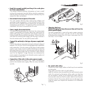
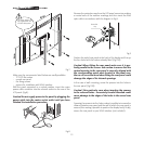
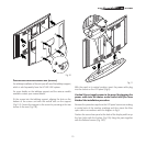
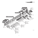
With the panel in its vertical position, insert the power cable plug
into the socket on the LCD panel (Fig.8).
Caution! Do not supply power to the panel by plugging the
power cable into the mains socket outlet until you have
finished the installation procedure.
Remove the protective caps from the LCD panel connectors making
a mental note of the number markings and then insert the fibre
optic cable in accordance with the diagram in Fig.9.
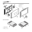
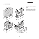
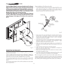
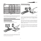
Position the curved rear panel at the back of the display and line up
the four holes with the bushes (Fig.12A) fixing the parts together
with the flathead screws (Fig.12B).
Fig.10
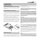
T
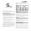
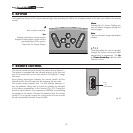
ABLETOP INSTALLATION WITH SUPPORT BASE (OPTIONAL)
For tabletop installation of the unit you will need the tabletop support,
which is sold separately from the HTL40 LINK system.
For more details on the tabletop support and the various models
available contact your nearest dealer.
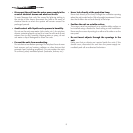
Fit the screen into the tabletop support, aligning the slots on the
bottom of the screen unit with the vertical tabs on the support
(Fig.11A). Secure the support to the screen by screwing in the two
screws in the rear (Fig.11B).