


12
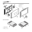
Fig.7
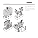
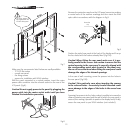
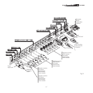
Make sure the components listed below are readily available:
- TFT-LCD flat screen
- curved rear panel.
- the fixing screws.
- spacers for installation with VESA interface
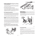
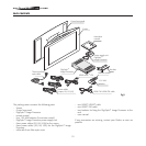
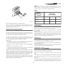
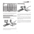
With the panel supported in a vertical position, insert the mains
power cable connector into the relevant socket on the rear of the
LCD panel (Fig.8).
Caution! Do not supply power to the panel by plugging the
power cable into the mains socket outlet until you have
finished the installation procedure.
Fig.8
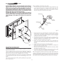
Remove the protective caps from the LCD panel connectors making
a mental note of the number markings and then insert the fibre
optic cable in accordance with the diagram in Fig.9.
Fig.9
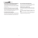
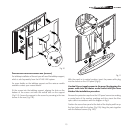
Position the styled rear panel at the back of the display and line up
the four holes with the bushes already fitted (Fig.10A).
Caution! When fitting the rear panel make sure it is per
-
fectly parallel to the screen. Use caution to ensure that the
central opening in the rear panel is correctly aligned with
the corresponding metal parts located in the panel rear:
the use of excessive force when fitting the rear panel could
damage the edges of its internal openings.
In the case of wall mounting, screw the spacers into the holes in
the rear panel (Fig.10B).
Caution! Take particular care when inserting the spacers
in the relevant holes. Excessively forceful insertion could
cause damage to the edges of the holes in the curved rear
panel.
Screwing the spacers into the holes makes it possible to increase the
distance between rear panel and the wall to which the rear panel is
secured, this making it possible to position the display freely. Finally,
secure the rear panel to your VESA interface (not included).
Protective
cap
The fixing system is
not supplied with the
HTL40 LINK system