


15
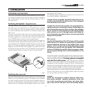
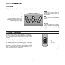
Fig.14
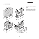
Avoid exposing the panel to direct light sources.
As far as possible it is also advisable to avoid placing light coloured
furniture or other objects with highly reflective surfaces in the im
-
mediate proximity of the screen.
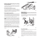
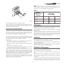
CONNECTING THE VIDEO SOURCES
Connect the cables from the video sources, the serial cable from
the external control unit and the optical fibre cables connection to
the rear panel of the DigiOptic™ Image Processor.
To obtain the best performance from the HTL40 LINK system, con
-
nect the various signal sources using good quality cables designed
for video applications (rated impedance 75 [IMG]).
Ensure that:
• the cables are routed in such a way that they do not present an
obstruction to people moving around the room;
• the connectors are inserted carefully to avoid damaging the
pins;
• the cables are not twisted or crushed;
• when disconnecting the cables the connectors are not violently
pulled out of the connectors on the various units.
Video sources (television receivers, VCRs, DVD players, etc.) often
feature several outputs. To obtain the best performance from your
system, carefully choose which output to use. Generally, the type
of signal offering the best picture quality is DVI-D, followed by RGB,
Components, S-Video and Composite Video, in that order.
However, the HTL40 LINK system is equipped with an excellent
Video Decoder and Deinterlacer and therefore even inferior quality
signals will produce high quality results.
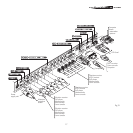
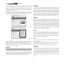
Table 1 shows the types of signals usually available for the most
common types of video sources and the corresponding input con-
nectors to use on the DigiOptic™ Image Processor.
Table 1
VIDEO
1
2
3
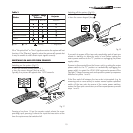
These inputs should be connected to a Composite Video signal
(CVBS) by means of a cable with an RCA connector.
The connector on the source is usually yellow and is frequently
labelled VIDEO.
Although other types of signals are preferable (since they allow better
picture quality), this is still the most common type of output, and
nearly all television receivers, videorecorders, DVD players, video
cameras, etc., are equipped with CVBS outputs.
S-VIDEO
4
5
These inputs should be connected to an S-Video signal by means
of a cable with a 4-pin mini-DIN type connector.
The corresponding output on the source can be identified by the
wording S-VIDEO or Y/C.
Almost as widespread as Composite Video, S-VIDEO is preferable
because it offers a clearer and sharper picture.
COMPONENT / RGBS
6
7
8
9
These inputs are composed of three sets of 5 RCA connectors
(5,6,7) and a set of 5 BNC connectors (8).
Each set of connectors is suitable for RGB and Component sig-
nals.
RGB signals can have the following synchronisations: composite
sync on the green signal (RGsB), H+V Composite Sync, or separate
H/V Sync.
Connect the R, G, B outputs of the source to the respective R, G, B
inputs of the DigiOptic™ Image Processor (taking care not to invert
the positions) and any synchronisation signals to the HV input or the
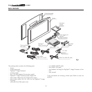
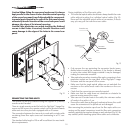
Protective
cap