


Power Preparations
Chapter 2 Power Preparations and Connections
36 Chapter 2 Power Preparations and Connections
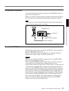
Connections for Cut Editing Using Two DSR-70/
70P Units — i.LINK Connections (Optional DSBK-140
Required)
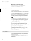
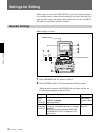
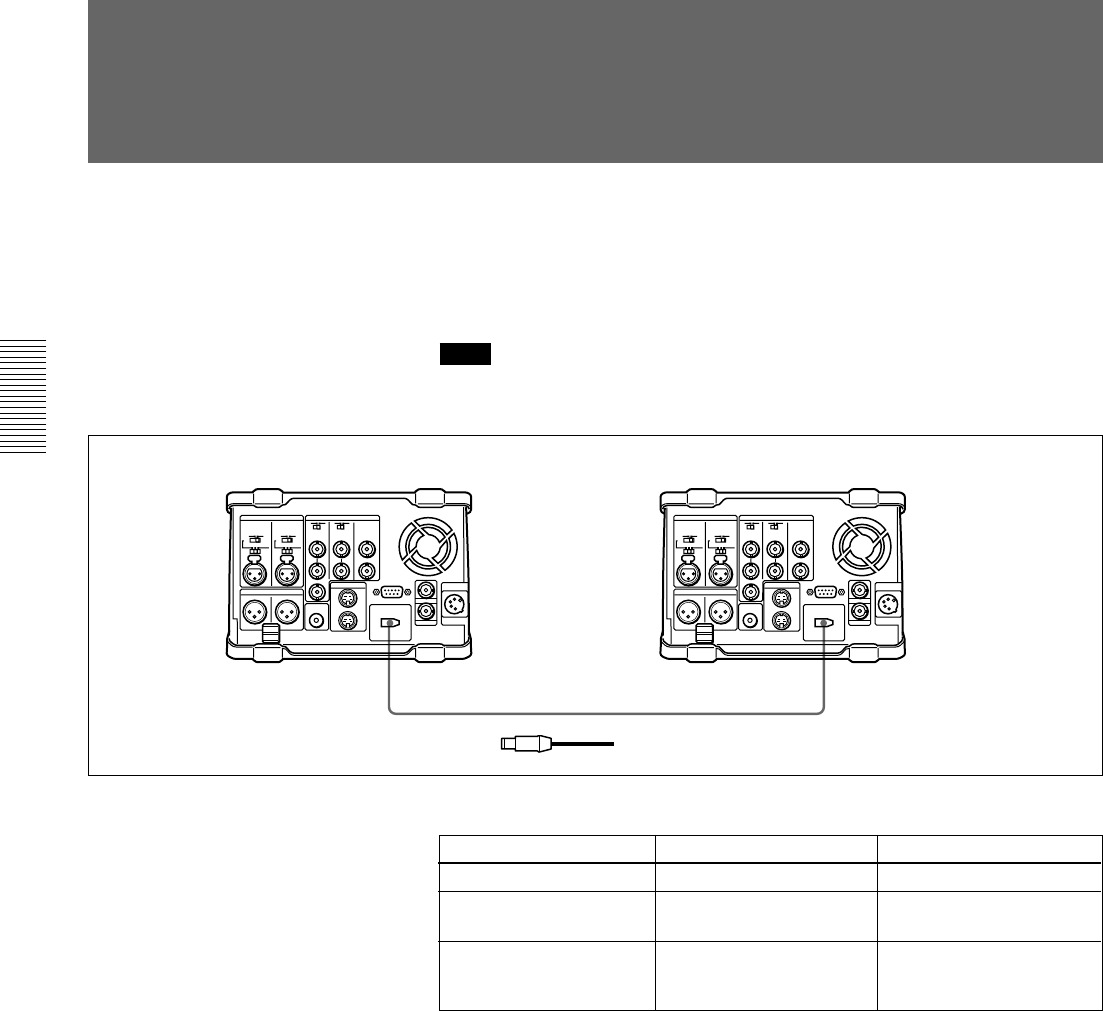
For a cut editing system using two DSR-70/70P units with an i.LINK
interface, the following figure shows an example of the connections.
Use the same configuration when dubbing signals in DVCAM format via
an i LINK interface.
Note
In this case, both of the recorder and player require the DSBK-140 i.LINK/
DV Input/Output Board.
DSR-70/70P (recorder)
DV IN/OUT DV IN/OUT
DSR-70/70P (player)
1 6-pin to 6-pin i.LINK/DV cable (supplied with the DSBK-140)
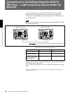
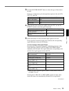
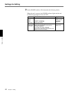
DSR-70/70P (recorder and player) settings
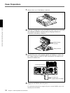
It is possible to combine two DSR-70/70P units using the optional BKNW-
225 Docking Kit (see page 125).
Also, for ease of carriage of the unit, you can use a shoulder belt (see page
126).
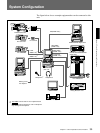
For more example editing system connections, see Chapter 8“Connections and
Settings” (page 113).
1
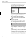
Switch/menu Recorder Player
REMOTE/LOCAL LOCAL REMOTE
Sub LCD menu general
setting item REMOTE
i.LINK i.LINK
Sub LCD menu home
page input video/audio
signal indication
i.LINK Other than i.LINK