


Chapter 12 Setup Menus
Chapter 12 Setup Menus 12-9
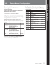
Menu items in the range 100 to 199, relating to the control panels (Continued)
Item number
107
108
109
111
115
116
117
Item name
REC INHIBIT LAMP
FLASHING
AUTO EE SELECT
FORCED EE WHEN
TAPE UNTHREAD
TSO PLAY
PHASE LOCK IN
VARIABLE X3 (DVW-
M2000/M2000P only)
JOG DIAL RESPONSE
CONTROL PANEL
SELECTION
Settings
Select whether or not to flash the REC INHI indicator when the function menu
item RECINH is set to OFF and the record inhibit plug on the cassette is pressed
in.
OFF : Do not flash the REC INHI indicator.
ON: Flash the REC INHI indicator.
When a digital cassette is inserted and the function menu item PB/EE is set to
EE, select the VTR modes in which input video and audio signals are
automatically handled in E-E mode.
When an analog cassette is inserted, regardless of the function menu setting the
PB mode is always selected.
S/F/R : In STOP/EJECT/F.FWD/REW modes
STOP: In STOP/EJECT modes
During tape threading and unthreading, and when no cassette is inserted, select
whether the setting of the function menu item PB/EE controls the PB/EE setting
for output signals.
OFF: Control by the function menu item PB/EE
ON : No control (always E-E signal)
Select whether or not to enable tape speed override mode.
DIS : Disable tape speed override mode.
TSO: Enable tape speed override mode.
Select whether or not to lock the capstan phase in ×3 variable speed play mode
when playing back a Betacam or Betacam SP cassette.
OFF : Do not lock.
ON: Lock.
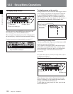
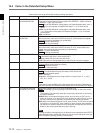
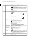
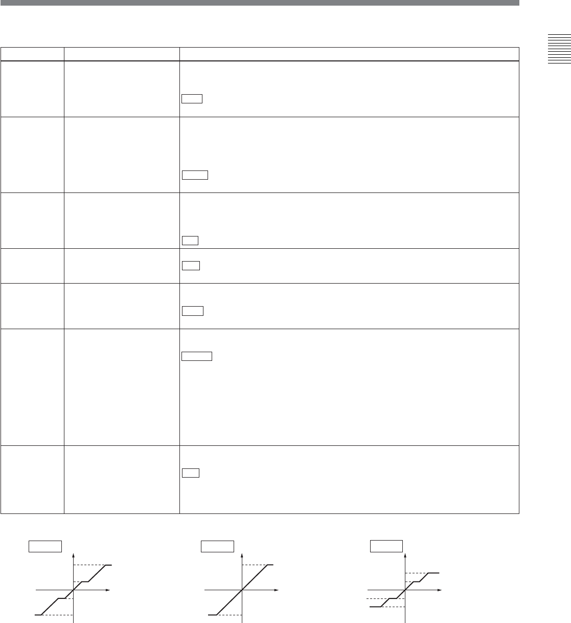
Select the tape speed characteristics for the search dial rotation rate (VTR
commands).
TYPE1 : Tape speed varies linearly over the range –1 to +1.
TYPE2: Tape speed varies stepwise as shown in the figure below
a)
over the
range –3 to +3. (Characterized by a zone around –1 and +1 where the tape
speed is independent of the search dial rotation rate)
TYPE3: Tape speed varies linearly over the range –3 to +3, as shown in the
figure below
b)
.
TYPE4: Tape speed varies stepwise as shown in the figure below
c)
over the
range –2 to +2. (Characterized by a zone around –1 and +1 where the tape
speed is independent of the search dial rotation rate)
Select the control panel function when the PANEL SELECT switch on the switch
panel is set to REAR.
SW : Only the control panel connected to the CONTROL PANEL connector on
the connector panel functions.
PARA: The control panels connected to the CONTROL PANEL connectors on
the switch panel and connector panel both function.
Speed
Rotation rate
SpeedSpeed
Rotation rate Rotation rate
(Continued)
(reverse)
a) b) c)
+3
+1
-1
-3
FWD
FWD
RVS
RVS
+3
-3
FWD
FWD
RVS
RVS
+2
+1
-1
-2
FWD
FWD
RVS
RVS
TYPE 3TYPE 2
TYPE 4
(forward)