


Chapter 12 Setup Menus
Chapter 12 Setup Menus 12-21
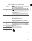
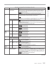
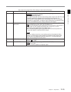
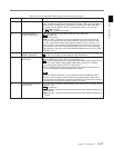
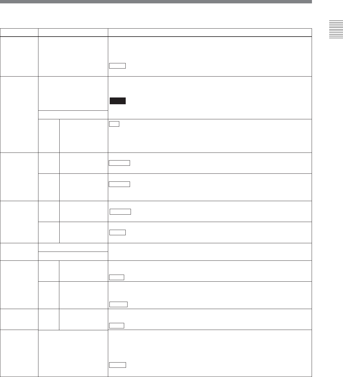
Menu items in the range 700 to 799, relating to video control
Item number
701
703
DVW-M2000/
2000
DVW-
M2000P/
2000P
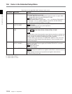
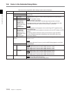
704
DVW-M2000/
2000
DVW-
M2000P/
2000P
705
Item name
SELECTION OF VIDEO/
SYNC DELAY
BLANK LINE SELECT
0 ALL LINE
12 ... LINE 12 ... LINE
19 19
20 LINE 20
9 ... 22 LINE 9 ... LINE 22
23 LINE 23
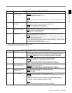
DECODE Y/C SEP MODE
Sub-Item
12 ... LINE 12 ... LINE
20 20
21... LINE 21 ... LINE
22 22
9 ... 22 LINE 9 ... LINE 22
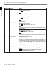
EDGE SUBCARRIER
REDUCER MODE
Settings
In E-E mode the video signal is output delayed with respect to the video input
signal by the time for video circuit processing. With this item, select whether or
not to delay the sync signal attached to the output video signal by an amount
corresponding to the delay.
SYNC : Delay the sync signal by the corresponding amount before attaching it.
VIDEO: Attach a sync signal with the same timing as the input signal.
Switch blanking on or off for individual lines in the vertical blanking interval. The
Y/C signal and odd/even fields are blanked simultaneously.
Note
For playback of an analog Betacam cassette (Betacam SP, etc.) regardless of the
setting of this item, the chrominance signal is blanked up to line 15.
- - - : Specify the blanking for each line separately.
BLANK: Regardless of the setting of other sub-items, blank all lines which can be
specified in this menu item.
THROU: Regardless of the setting of other sub-items, switch off blanking for all
lines which can be specified in this menu item.
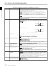
Specify blanking for lines 12 to 19.
BLANK : Carry out blanking.
THROU: Switch off blanking.
Specify blanking for lines 20.
BLANK : Carry out blanking.
HALF: Carry out half-blanking.
THROU: Switch off blanking.
Specify blanking for lines 9 to 22.
BLANK : Carry out blanking.
THROU: Switch off blanking.
Specify blanking for lines 23.
HALF : Carry out half-blanking.
THROU: Switch off blanking.
Select the method of processing the input video signal in the vertical blanking
interval, independently for each line.
Make the selection for lines 12 to 20.
BPF: Carry out Y/C separation.
B&W : Treat all as luminance signals.
Make the selection for lines 21 to 22.
BPF: Carry out Y/C separation.
B&W: Treat all as luminance signals.
COMB : Process with an appropriate Y/C separation.
Make the selection for lines 9 to 22.
BPF: Carry out Y/C separation.
B&W : Treat all as luminance signals.
During recording and playback of a composite signal, in the playback circuit the
edge subcarrier reducer (ESR) is automatically switched on or off according to
the VTR operation. When recording a “Non-Standard” signal, for example, if the
color edges are not as good as with a proper signal, the ESR can be forced on.
This item makes this selection.
AUTO : ESR is switched on and off automatically.
ON: ESR operation is forced on.
(Continued)
Sub-Item