


Chapter 2 Location and Function of Parts
Chapter 2 Location and Function of Parts 2-5
AES/EBU/ANA
SDI
DATA 5 6 7 8
MIX
1 2 3 4
OVER
dB dB
EMPH
L R
20
10
2
1
0
0
-10
-20
-30
-40
-60
-1
-10
-20
-40
-2
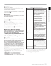
Input signal indicator
DATA indicator
MIX indicator
OVER indicator
Level meter
Input channel
indicator
Monitor channel L
and R indicators
EMPH indicator
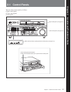
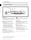
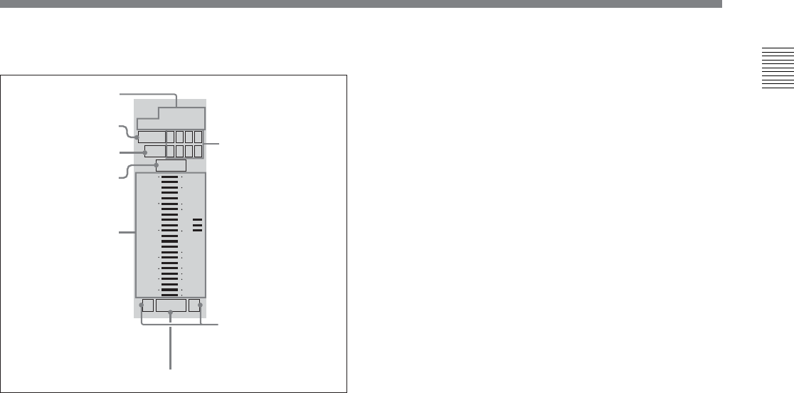
3 Audio setting display section
Input signal indicator: Indicates the currently
selected input signal (‘SDI’, ‘AES/EBU’, ‘ANA’
for analog) for the corresponding audio input
channel.
DATA indicator: Lights when the corresponding
audio track (audio channel on the tape) is put into
data mode.
For details of the data mode, refer to the Maintenance
Manual Volume 1.
MIX (mixing) indicator: Flashes when a mixing
setting operation is enabled for the corresponding
audio track. The indicator showing the number of
the selected input channel lights.
OVER indicator: While the unit is in recording or
playback mode, this lights when the level of the
audio signal on the corresponding channel exceeds
the maximum level that can be indicated on the
level meter.
Level meter: Displays the audio signal level when
the unit is in recording, E-E
1)
, or playback mode.
You can use the setup menu to switch the display
mode between PEAK.0 (0 dB is maximum level)
and REF.0 (0 dB is the reference level). You can
also use the DISPLAY FULL/FINE button 2 to
enlarge the display only near the reference level.
Input channel indicator: Indicates the input channel
from which audio signals are recorded on the
audio track. Two numbers light to indicate that
signals from the corresponding input channels are
mixed for recording.
Monitor channel L and R indicators: Indicate
whether or not the signals of the track are output
to the MONITOR OUTPUT L and R connectors
or the PHONES jack. ‘L’ lights to indicate output
to the left monitor channel, and ‘R’ lights to
indicate output to the right monitor channel.
EMPH (emphasis) indicator: While the unit is in
recording or playback mode, this lights when the
emphasis setting is on for the audio signal on the
corresponding track.
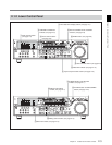
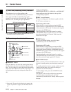
4 Audio signal selection buttons (CH1 to CH4,
CUE)
The function of these buttons depends on the signal
selection mode set with the audio selection function
selector buttons (INPUT, MIXING) 1 as follows.
Input signal selection mode (the input signal
indicator flashes): The buttons in the upper row
select signals for each audio input channel.
Each time you press the CH1 (CH2, CH3, CH4)
button, the selected signal cycles through SDI
(channel 1 (2, 3, 4)) t SDI (channel 5 (6, 7, 8))
t AES/EBU t ANA(analog) t SDI (channel 1
(2, 3, 4))...
Press the INPUT button to confirm the input
signal selections.
Mixing setting mode (the MIX indicator flashes):
The buttons in the lower row (REC row) select the
tracks (audio channels on the tape) to contain the
mixed signals. In the audio setting display section,
the MIX indicator for the corresponding track
flashes. The buttons in the upper row (EXT row)
select the input channel signals to record on the
corresponding track. By pressing two buttons at
the same time, you can specify that the signals of
two input channels be mixed for recording.
For example, if you want to record the mixed
signals of input channels 1 and 4 on track 3, press
the CH3 button in the lower row (REC row), and
then simultaneously press the CH1 and CH4
buttons in the upper row (EXT row).
1) E-E mode: Abbreviation of “Electric-to-Electric mode”.
In this mode, video and audio signals input to the VTR
are output after passing through internal electric circuits,
..........................................................................................................................................................................................................
but not through magnetic conversion circuits such as
heads and tapes. This can be used to check input signals
and for adjusting input signal levels.