


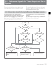
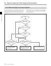

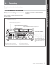
3-2 Reference Signals for Video Output and Servo System
Chapter 3 Preparations
3-8 Chapter 3 Preparations
TCR . 23 : 5 9 . 4 0 . 18 *
PSHUTTLESTILL
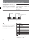
3-4 Superimposed Character Information
When the function menu item CHARA is set to ON,
the video signal output from the COMPOSITE VIDEO
OUTPUT 3 (SUPER) connector or the SDI OUTPUT
3 (SUPER) connector contains superimposed character
information, including time code, menu settings, and
alarm messages.
Adjusting the character display
You can adjust the position, size and type of the
superimposed characters using setup menu items 002,
003, 005, 009, and 011.
For details, see Section 12-3 “Items in the Basic Setup
Menu” (page 12-5).
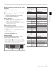
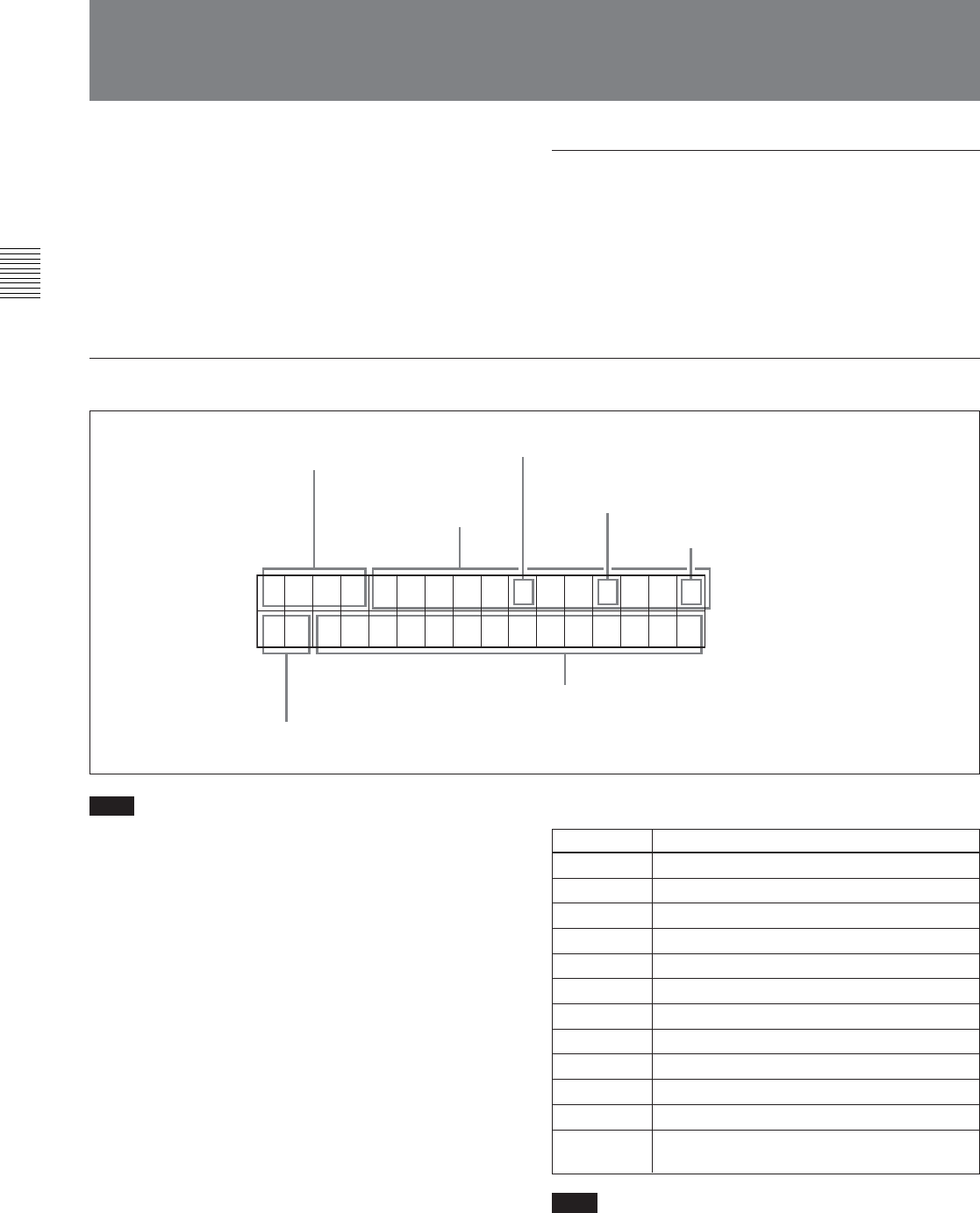
Information displayed
1 Type of time data
Note
If the time data or user’s bits cannot be read correctly,
they will be displayed with an asterisk. For example,
“T*R”, “U*R”, “T*R.” or “U*R.”.
Note
The display shown above corresponds to the factory
default settings of the unit.
Changing the setting of setup menu item 005 allows
different time data to be displayed in the lower line of
the display.
For details, see Section 12-3 “Items in the Basic Setup
Menu” (page 12-5).
1 Type of time data
Time data
2Time code reader drop frame mark
(for 525-line mode only)
4VITC field mark
6Operation mode
5Recorder/player selection
3Time code generator drop frame mark (for
525-line mode only)
Display
CTL
TCR
UBR
TCR.
UBR.
TCG
UBG
IN
OUT
AI
AO
DUR
Meaning
CTL counter data
LTC reader time code
LTC reader user’s bits
VITC reader time code
VITC reader user’s bits
Time code generator time code
Time code generator user’s bits
IN point
OUT point
Audio IN point
Audio OUT point
Duration between any two of the four edit
points (IN, OUT, audio IN, audio OUT)