


Chapter 1 Overview 13
Chapter 1 Overview
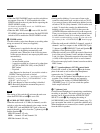
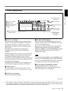
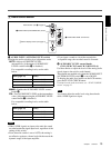
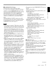
3 Audio control section
a AUDIO INPUT (AUTO/MANU/FIX) switch
Switches the audio recording level adjustment mode.
AUTO : Adjusts AUDIO REC LEVEL
automatically. (Adjustment of AUDIO REC
LEVEL control knobs 2 is disabled.)
For acceptable recording levels, see the table
below.
MANU : Enables the AUDIO REC LEVEL control
knobs 2.
FIX : Fixes AUDIO REC LEVEL at the intermediate
value. (Adjustment using the AUDIO REC LEVEL
control knobs 2 is disabled.)
For acceptable recording levels, see the table
below.
• When i.LINK signals are input to the unit, the sound
recorded retains the signal input level, regardless of the
setting of this switch.
• Even when this switch is set to AUTO, the setting is
not effective against a volume level which exceeds the
dynamic range of the input amplifier.
• If you input a sound at a level that exceeds the
acceptable range, the recorded sound is distorted.
b AUDIO REC LEVEL control knobs
(CH-1 (DUB CH-3) and CH-2 (DUB CH-4))
Use these knobs to adjust the levels of the analog audio
signals input to the unit for each channel.
These knobs are enabled only when the AUDIO INPUT
(AUTO/MANU/FIX) switch 1 is set to MANU.
To display the audio level meters on the LCD monitor,
press the STATUS CHECK button.
For details on the audio level meter, see “STATUS CHECK
screen” on page 25.
You cannot adjust the audio level using these knobs
while i.LINK signals are input.
1 AUDIO INPUT (AUTO/MANU/FIX) switch
2 AUDIO REC LEVEL control knob
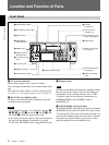
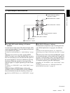
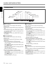
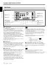
EJECT button (see qd in page 8)
1Monitor display section (see page 9)
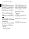
AUDIO INPUT LEVEL
switch (page 16)
Acceptable level
(max.)
–10 +18 dBu
–2 +24 dBu
+4 +30 dBu
AUDIO INPUT LEVEL
switch (page 16)
Acceptable level
(max.)
–10 +18 dBu
–2 +24 dBu
+4 +30 dBu
Notes
Note