


6 Chapter 1 Overview
Chapter 1 Overview
Location and Function of Parts
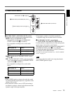
a q (cassette) indicator
Lights when a digital video cassette is loaded.
Does not light up when there is no cassette loaded in the
unit.
This indicator blinks while a cassette is being ejected.
For details, see “Inserting/Ejecting Cassettes” on page 29.
b KEY INH (key inhibit) switch
Turning on this switch disables all buttons to prevent
accidental button operations.
• Even when this switch is set to ON, the switches 5,
6, q;, qs, and 3-1, the knobs 7 and 3-2, and
the switch 4 on the rear panel can be used.
• Even when you set this switch to ON, you can operate
the unit with the Remote Commander, or via the
LANC jack, CONTROL S jack, and HDV/DV jack.
c Remote sensor
In addition to the Remote Commander supplied with the
unit, the unit accepts signals from any Sony Remote
Commander whose command mode is set to VTR4.
To disable control from a Remote Commander, set
[COMMANDER] in the [OTHERS] menu to
[CONTROL S].
d ON/STANDBY switch and lamp
The ON/STANDBY lamp lights up in green or red when
the POWER switch on the rear panel of the unit is in the
“|” position (ON). Press this switch while the lamp is lit
in red (in the standby mode) to turn the unit on, and the
lamp lights up in green. When you press this switch
again, the unit goes into the standby mode.
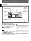
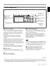
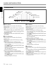
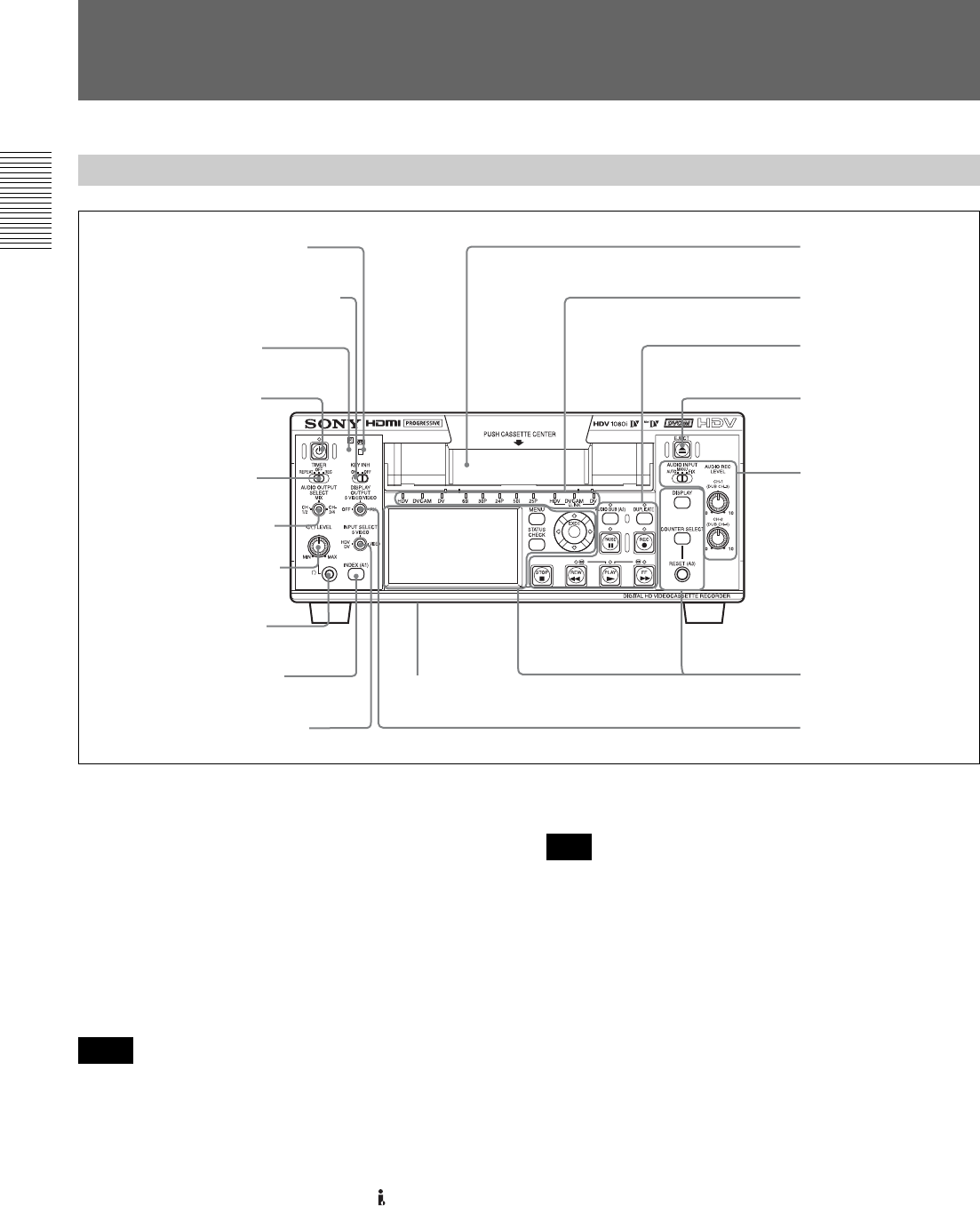
Front Panel
3 Remote sensor
1 q (cassette) indicator
4 ON/STANDBY
switch and lamp
1 Monitor display section
(see page 9)
2 Tape transport control
section (see page 11)
2 KEY INH (key inhibit) switch
7 5/i LEVEL control
knob
5 TIMER switch
8 i (phones) jack
6 AUDIO OUTPUT
SELECT switch
qs DISPLAY OUTPUT
switch
q; INPUT SELECT switch
qd EJECT button
9 INDEX (A1) button
qf Cassette
compartment
3 Audio control section
(see page 13)
4 Indicator section
(see page 14)
qa Speaker (Bottom panel)
Notes
Note