


20 Chapter 1 Overview
Chapter 1 Overview
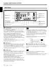
Location and Function of Parts
• The unit is only compatible with standard video
signals. If you input the types of video signals shown
below, recorded picture and sound may be distorted.
– Signals from some home game machines
– Blue background screen or gray background screen
images from a consumer VCR
– Pictures played at a speed other than normal by a
VCR that does not have TBC (Time Base Corrector)
– Video signals in which the sync signals are distorted
– Signals from a defective cassette (tape or recording
condition is bad) played by an analog VCR that does
not have TBC
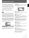
• When DVCAM/DV signals which are input from the
HDV/DV jack, or video signals which are from the
VIDEO IN jacks or S VIDEO IN jacks, are output to
each analog output jack, the distortion of the video
signals occurs at the bottom of the TV monitor display
due to the jitter. Depending on the display area of the
TV monitor you have, the distortion of the picture may
appear at the bottom of the screen. This is not a
malfunction.
Pictures may be distorted or not be displayed
depending on the TV monitors. This will not appear
while recording with the unit.
Be aware of these phenomena when you connect other
recording device via the analog jacks of the unit.
• Depending on the TV monitor being connected, the
screen may blink or be distorted when DVCAM/DV
signals which are input from the HDV/DV jack, or
video signals which are from the VIDEO IN jacks or
S VIDEO IN jacks, are output to the VIDEO OUT
jacks.
Be aware of these phenomena when you connect other
recording device to these jacks. This will not appear
while recording with the unit.
• During recording or in EE mode, the subcarrier of the
color signal to be output from the unit is not
synchronized with the horizontal sync signal. The
color of the picture or the horizontal position of the
picture may be distorted depending on the type of
monitor connected to the unit.
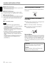
• To output video signals to the VIDEO, S VIDEO, or
COMPONENT OUT jacks without text data, set the
DISPLAY OUTPUT switch to OFF, or press the
DATA CODE or SEARCH SELECT button on the
remote commander.
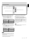
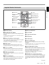
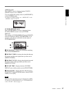
j AC IN connector
Connects to an AC outlet using the supplied power cord.
Even if the unit is in the standby mode, it consumes
power. To turn the power off completely, press the “a”
(OFF) marked side of the POWER switch qs.
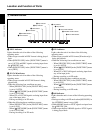
k RESET button
If you press this button with the tip of a ballpoint pen or
similar tool, the following settings are initialized.
– [CLOCK SET] (page 81) and [60i/50i SEL] (page 82)
in the [OTHERS] menu.
– The settings on the unit other than the menu settings.
l POWER (main power) switch
The main power switch of the unit. When this switch is
in the “|” position, the ON/STANDBY lamp on the front
panel lights up in green. (In the standby mode, the ON/
STANDBY lamp lights up in red.)
When you do not intend to use the unit for a long time,
press the “a” (OFF) marked side of the POWER
switch.