


Chapter 1 Overview 25
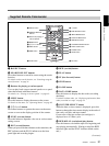
Chapter 1 Overview
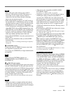
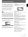
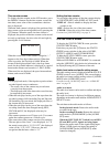
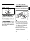
Time counter screen
To display the time counter on the LCD monitor, press
the DISPLAY button. On the time counter screen, the
time data (count value of the counter/time code/user
bits) is displayed.
While the time counter is displayed, the position of the
time counter can be moved up and down by pressing the
J/j buttons. When the small size time counter is
displayed, the position of the time counter can be moved
not only up and down, but also to the left and right by
pressing the K/k buttons.
When the count value of the counter is negative, “–”
appears as the first digit (leftmost digit). When that
value is positive, the first digit is blank. When the
format of the displayed time code is the drop frame
mode, the drop frame indicator is displayed as a period
between the minutes and seconds (i.e., 00:12.58:00).
When user bits are displayed, the space between hour,
minute, and second is blank.
• In the playback mode, if the tape has a portion where
recorded signals are not continuous:
– The count value of the counter may not advance
correctly from that portion.
– The displayed value of the time code or user bits may
be temporarily inaccurate.
• When the unit plays back a part of the tape where the
recorded systems of 60i (including 24p and 30p) and
50i (including 25p) are mixed, the displayed value of
the counter may be inaccurate.
• When the unit plays back a part of the tape where the
recording format has been changed among HDV,
DVCAM and DV, the displayed value may be
inaccurate.
• The counter operates on a ±12-hour cycle. You cannot
make the counter operate on a 24-hour cycle.
• The count value of the counter consists of seven digits.
The tens place of the “hour” is not displayed. (i.e., If
the actual count value is “11:22:11:22”, the displayed
value will be “1:22:11:22.”) However, the unit
recognizes that the hours value is “11.”
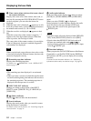
Setting the time counter
You can adjust the settings of the time counter display
in [COUNTER SET] in the [DISPLAY SET] menu.
DISPLAY : Selects whether to display the time
counter or not.
SIZE : Selects the size of the time counter.
COLOR : Selects the color of the time counter.
For details on [COUNTER SET], see page 74.
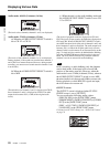
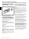
STATUS CHECK screen
To display the STATUS CHECK screen, press the
STATUS CHECK button.
Each time you press the J/j button, the STATUS
CHECK screen switches in the order of AUDIO,
OUTPUT, ASSIGN, and CUSTOM REPEAT.
To hide the STATUS CHECK screen, press the
STATUS CHECK button again.
While an HVR-DR60 or an HVR-MRC1 is connected
using the HDV/DV jack, the device information can
be displayed using the J/j buttons of the unit.
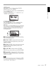
Audio level meter and audio setting screen
The audio setting screen is displayed when the STATUS
CHECK screen is set to [AUDIO]. This screen displays
the audio level meter and the setting values of [AUDIO
MONI] in the [AUDIO SET] menu.
For details on the [AUDIO SET] menu, see “AUDIO SET
menu” on page 76.
Audio level meter
The audio level meter can be used to confirm and adjust
the audio level.
The audio level meter is displayed in different patterns,
depending on the audio mode and the AUDIO OUTPUT
SELECT switch.
The unit detects the audio mode as follows:
In the playback mode: Detects the audio mode
recorded on the tape.
In the recording/EE mode: Detects the selected
audio mode in [AUDIO MODE] of the [AUDIO
SET] menu.
When the INPUT SELECT switch is set to HDV/
DV and HDV or DV signals are being input:
Detects the audio mode of the signals being input.
(When i.LINK signals are input, the setting of
[AUDIO MODE] in the [AUDIO SET] menu
cannot be changed.)
Notes
00:10:26:12
(Continued)