


16 Chapter 1 Overview
Chapter 1 Overview
Location and Function of Parts
a S VIDEO jacks
To connect a device equipped with S video jacks, use
the S VIDEO jacks on the unit.
If you use the S VIDEO jacks, you can input/output
high-quality video with less signal quality deterioration
than if connected to the standard VIDEO jack.
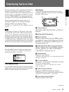
When the DISPLAY OUTPUT switch on the front
panel is set to S VIDEO/VIDEO or ALL, text data such
as the time code, menus, and alarm messages are
superimposed on an external monitor connected to the
S VIDEO OUT jack (page 23).
For details on the output of the S VIDEO jacks, see “Notes on
all video output jacks” on page 19.
b VIDEO jacks
Use these jacks to input and output analog video signals.
Text data is superimposed on a monitor in the same
way as with an S VIDEO jack connection (page 23).
For details on the output of the VIDEO jacks, see “Notes on
all video output jacks” on page 19.
c AUDIO jacks
Use these jacks to input and output analog audio signals.
During normal recording, sounds are recorded onto
channels 1 and 2. During audio dubbing, sounds are
dubbed onto channels 3 and 4.
You can select audio signals to be output with the
AUDIO OUTPUT SELECT switch (page 7).
When the audio mode is FS32K (4 channel), if you set
the AUDIO OUTPUT SELECT switch to MIX, the
audio output level becomes 50% (–6 dB) of the original
audio level on each channel.
• During audio dubbing, CH-1/3 and CH-2/4 of the
AUDIO IN jacks function as the channel 3 and channel
4 input jacks, respectively.
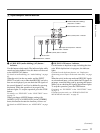
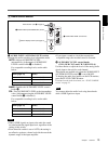
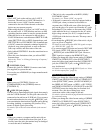
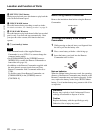
• To input balanced audio signals via the AUDIO IN
jacks, use a conversion cable as shown below. (The
COLD side is open.)
For details on conversion cables, refer to the instruction
manual of the devices you use.
d AUDIO INPUT LEVEL (–10/–2/+4) switch
Select one from –10 dB, –2 dB, or +4 dB, according to
the audio level of the signal input via the AUDIO IN
jacks.
If this switch setting is not appropriate, clipping
distortion or noise may occur.
For more information on the setting of this switch, see “When
you set the AUDIO INPUT LEVEL switch:” on page 89.
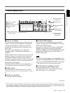
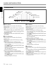
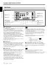
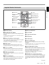
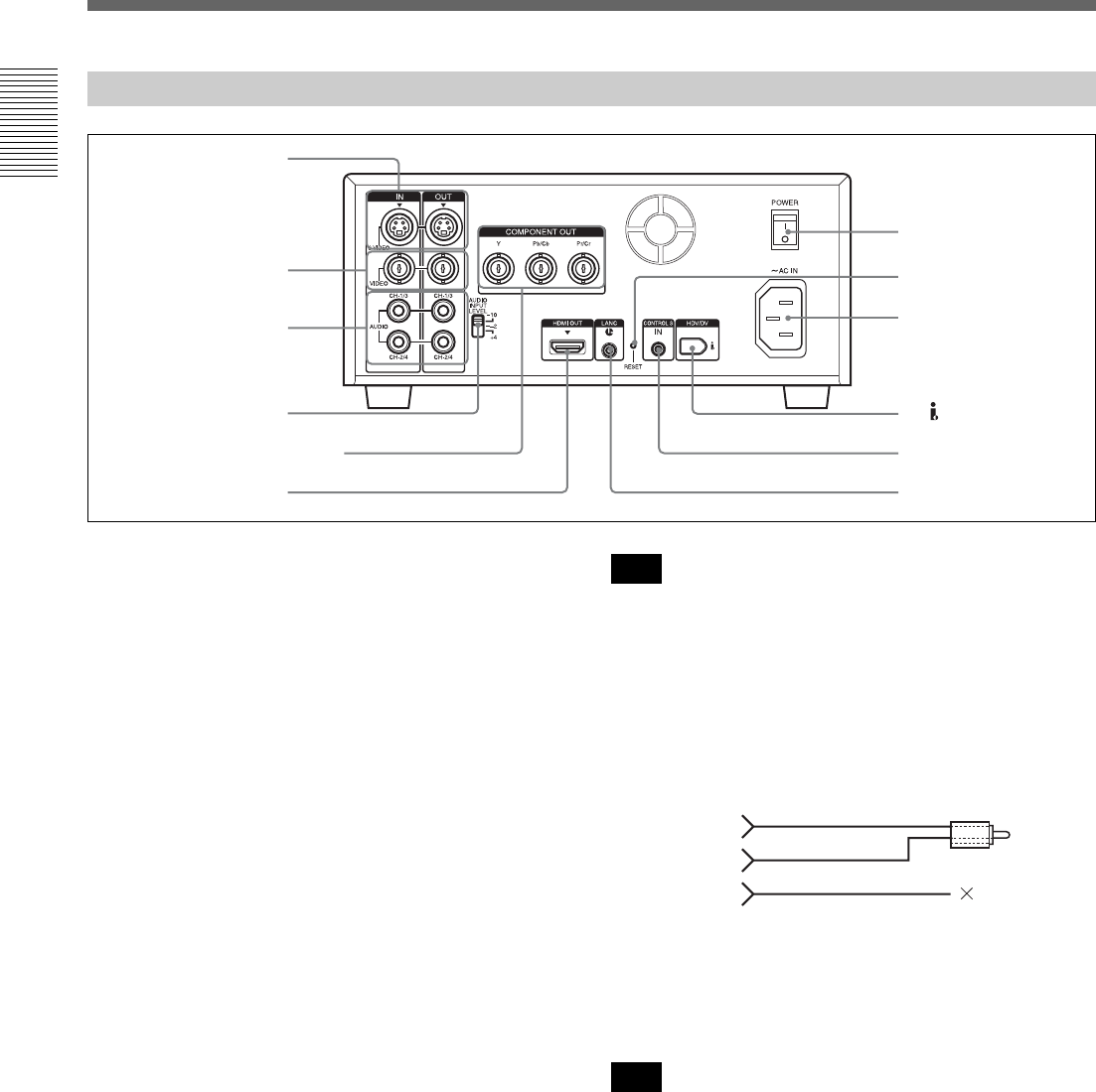
Rear Panel
1 S VIDEO jacks
3 AUDIO jack
2 VIDEO jacks
qa RESET button
q; AC IN connector
8 CONTROL S jack
9 HDV/DV jack
7 LANC jack
qs POWER switch
4 AUDIO INPUT
LEVEL switch
6 HDMI OUT jack
5 COMPONENT OUT jacks
Note
Note
COLD
HOT
GND