


2–Pump 12-Station Controllers Chapter 3: Installation 15
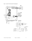
Connecting the Control Panel to Vacuum Hoppers
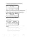
Refer to the wiring connection diagram in Figure 1 on the next page that applies to your
application.
Note: Wire size depends on control voltage, distance, number of vacuum
hoppers, and the number of wires in each raceway. Consult a qualified
electrician.
1. On 24 VDC control voltage systems, run a common +24 VDC wire and a common 0
(zero) VDC wire from the controller to each vacuum hopper in the system.
Note: For safety, make sure that the +24 volt line is fused. The size of the
fuse depends on the number of stations installed.
A 4 amp fuse is sufficient for a 12-station installation.
2. On all systems, run two wires to each vacuum hopper: one each from the controller
to the Bin-Full switch (LS) and to the Atmospheric/Sequence-T solenoid (SOL)
valve.
3. Make sure that the solenoid and the proximity switch (if supplied) on vacuum
hoppers are the same voltage (24 VDC) as the control panel voltage. Consult the
control panel serial tag and the solenoid valve nameplates.
4. Wire size depends on control voltage, distance, number of vacuum hoppers, and the
number of wires in each raceway. Consult a qualified electrician.
5. Properly ground each hopper to reduce static build up generated by material
conveying.
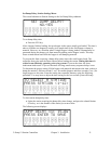
Connecting the Control Panel to the Pump Package
1. Wire the pump package motor starter coil (M) to the terminal provided in the control
panel enclosure.
2. Wire the pump package vacuum relief valve solenoid (SOL A) to the terminal
provided in the control panel enclosure.
3. Wire the pump package vacuum switch (VS) to the terminal located in the control
panel enclosure.
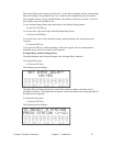
4. On vacuum pumps with blowback, wire the pump package blowback solenoid (SOL
B) to the terminal located in the control panel enclosure.
5. On 24 VDC control voltage systems, run a common +24 VDC wire and a common 0
(zero) VDC wire from the controller to each pump package in the system.