


2–Pump 12-Station Controllers Chapter 4: Operation 37
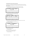
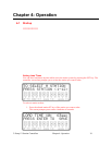
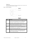
Station Icons
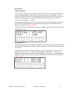
Below the text portion of the screen, 12 station icons display the status of each station in the
system. Each station icon contains four segments.
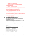
Figure 3: Station Icon Segments
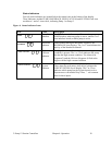
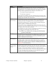
Label Description
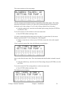
Segment 1
The top segment indicates the status of the valve above each station. When
the valve is open (control output energized), this icon highlights. In Single
Pump mode, only one valve indicator is active at a time. In Dual Pump
mode, up to two valve indicators can be active at a time. When this
indicator flashes, it indicates the assignment of a priority convey.
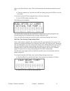
Segment 2
The center square segment indicates the existence of a station specific alarm
condition. The alarm is typically related to a No Convey condition, but can
also indicate the station with a high vacuum condition.
Segment 3
Located on the bottom of the station icon, the lower segment indicates the
station demand input. This is a real time indicator, displaying when the
station demand input is active. This indicator may toggle on and off during
the load cycle, and should be considered normal.
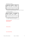
Segment 4
Segment 4 is the indicator word ON, located below the station icon. When
ON displays, the related station loads when the system senses a demand
signal. When ON does not display, the station demand input signal is
ignored and the related station does not load. Segment 4 blinks with
Segment 2 in a high vacuum condition.